
Method and apparatus for preventing overloads of power distribution networks

a technology of power distribution network and overload prevention, which is applied in the direction of electric devices, process and machine control, instruments, etc., can solve the problems of affecting the electrical design of data centers, affecting the use of electrical facilities, and only useful measurements and specifications

Inactive Publication Date: 2007-06-28
SCHNEIDER ELECTRIC IT CORP
View PDF67 Cites 72 Cited by
  • Summary
  • Abstract
  • Description
  • Claims
  • Application Information

AI Technical Summary

Benefits of technology

This system provides accurate and dynamic management of power distribution, preventing overload conditions and ensuring continuous operation of critical systems by adjusting power usage and temperature control, thereby enhancing the reliability and efficiency of data center power infrastructure.

Problems solved by technology

One of the major problems confronted by designers of these data centers is the requirement to route facility power to each of these racks of equipment.
These measurements and specifications are only useful for equipment for which the current draw is substantially static, which in the past was true for typical computing equipment.
The variability of the power draw of computers complicates the electrical design of data centers.
Because of conservative approaches taken in determining nameplate values, they are often greater than even worst case values for a given computer, and accordingly are of little use to an electrical facility designer.
Several problems may occur when circuit branches are designed based on measured power draw values of computers.
First, the wiring used in power routing circuits may be undersized for full load conditions, and second, when one or more of the computers powered from a branch are operated at full load, the current drawn may exceed the circuit breaker value for the branch, causing the circuit breaker to trip and disconnect power to the computers.
For critical applications of computers, any such power interruption is often unacceptable.
Further, to prevent power interruptions to critical computers, it is common to use uninterruptible power supplies (UPSs) for these computers.
The variability of the power draw in newer computers makes it difficult to properly size a UPS for these applications.

Method used


Image

  • Method and apparatus for preventing overloads of power distribution networks
  • Method and apparatus for preventing overloads of power distribution networks
  • Method and apparatus for preventing overloads of power distribution networks

Examples


Embodiment Construction

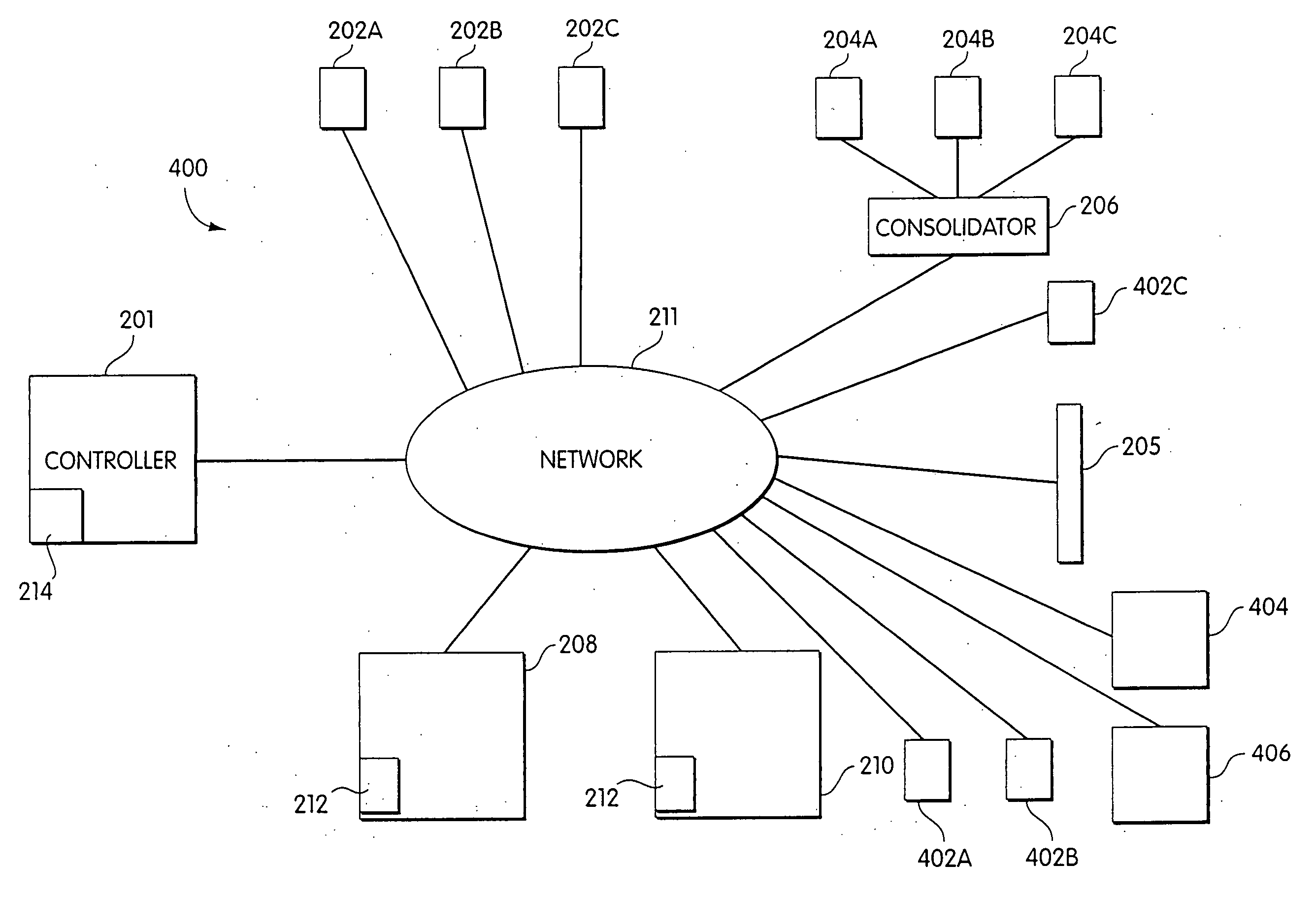
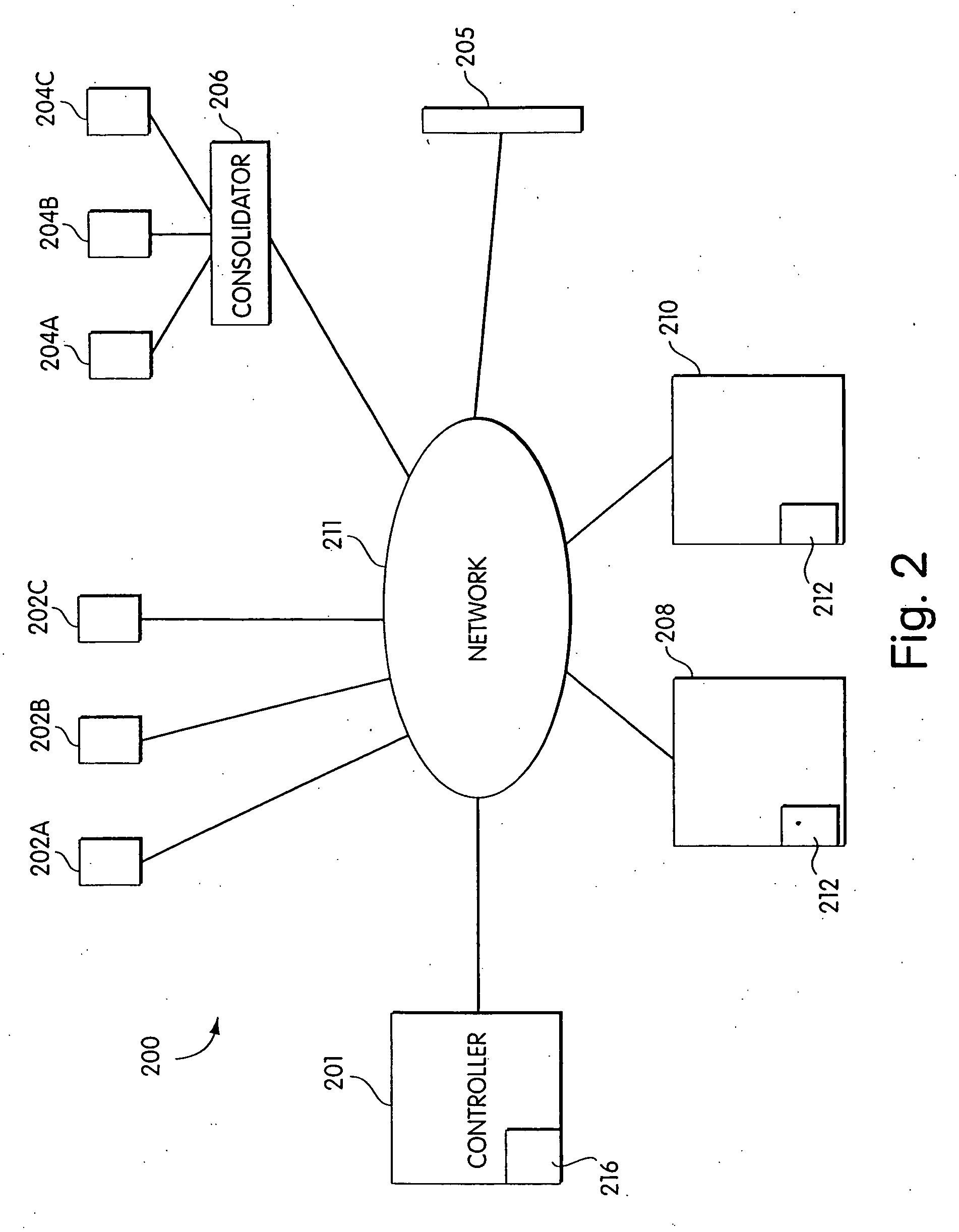
[0025] Embodiments of the present invention that provide methods and systems for monitoring and controlling power distribution in data centers will now be described. As understood by those skilled in the art, embodiments of the present invention are not limited for use in data centers, but may also be used in other facilities in which it is desired to monitor and control power distribution. Further, embodiments of the present invention may also be used aboard ships, airplanes or other mobile platforms where it is desired to monitor and control power distribution.

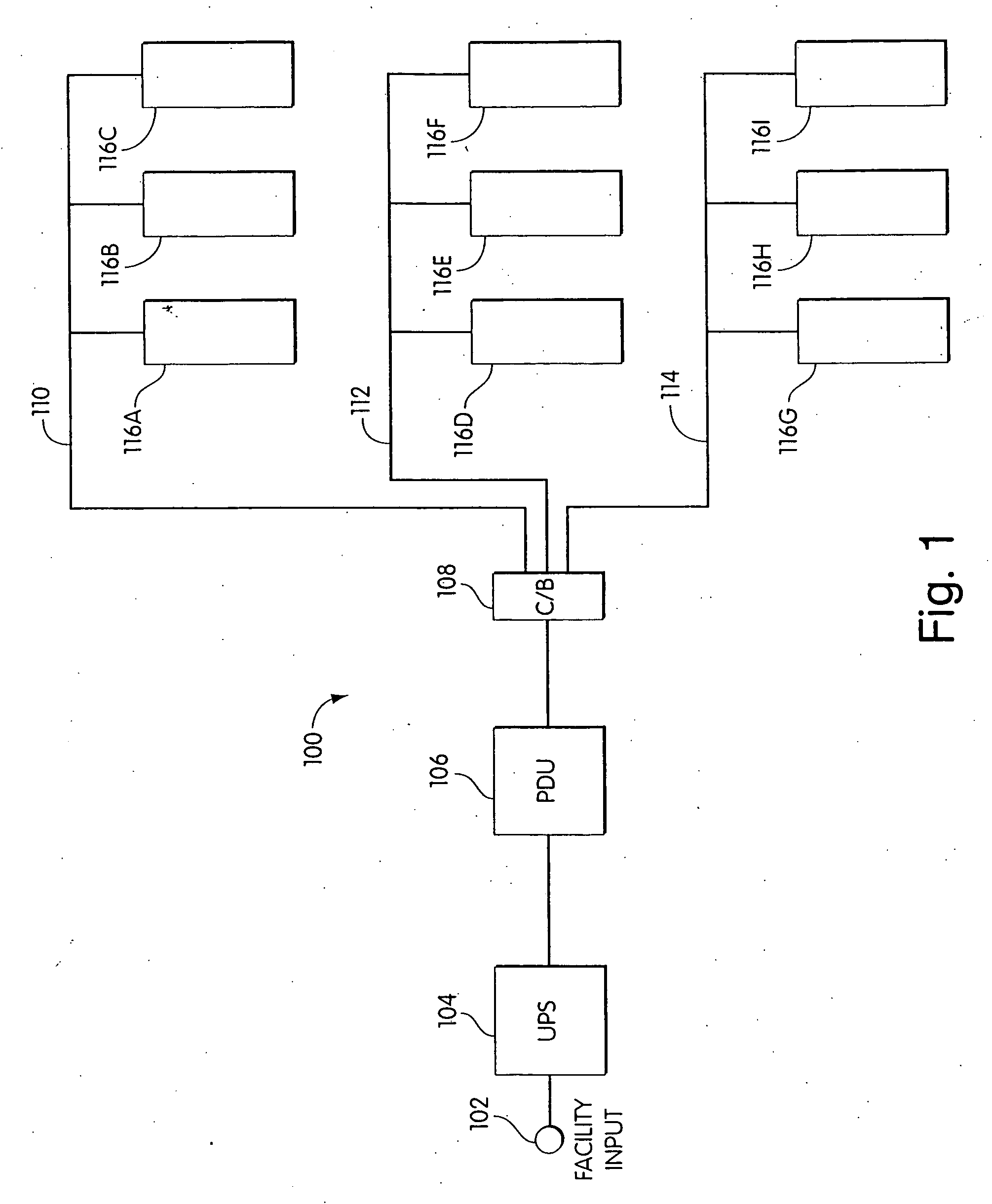
[0026]FIG. 1 provides a diagram of a typical power distribution system 100 for a data center. The power distribution system 100 includes a facility input power port 102, an uninterruptible power supply (UPS) 104, a power distribution unit (PDU) 106, a 108, and three power distribution branches 110, 112 and 114. In FIG. 1, the power distribution system is used to power nine loads 116a-1116i. As is known to those skilled in t...


PUM


Abstract

Systems and methods for monitoring power in power distribution systems are provided. In one aspect, a system for monitoring power includes a power monitoring device that measures a value of at least one characteristic of power provided to a branch of a power distribution system. The power monitoring device includes an output that provides the value measured. The system further includes a controller having an input to receive the value measured and an output that couples to a first device powered by the branch to send a maximum power signal to the first device to command the first device to operate at a percentage of maximum power.

Description

RELATED APPLICATIONS [0001] This application is a continuation of U.S. patent application Ser. No. 10 / 788,200, filed on Feb. 26, 2004, which is a continuation of U.S. patent application Ser. No. 10 / 038,701, filed on Jan. 2, 2002 (now U.S. Pat. No. 6,721,672), which both are incorporated herein by reference.FIELD OF THE INVENTION [0002] The present invention relates generally to methods and apparatus for measuring current or power delivered to loads in power distribution networks, and more specifically, to methods and apparatus for preventing overload conditions in power distribution equipment used to power equipment having variable input power requirements. BACKGROUND OF THE INVENTION [0003] The proliferation of the Internet has created a need for large scale data centers that contain tens, if not hundreds, of racks of computing equipment, such as servers and routers. One of the major problems confronted by designers of these data centers is the requirement to route facility power t...

Claims


Application Information

Patent Timeline
Patent Type & Authority Applications(United States)
IPC IPC(8): G06F19/00H02J3/14
CPCH02J3/14H02J2310/40Y04S20/222Y04S20/244Y02B70/30Y02B70/3225
Inventor SPITAELS, JAMESRASMUSSEN, NEIL
Owner SCHNEIDER ELECTRIC IT CORP
Learn More