
Cooling device for use with a projection apparatus

a cooling device and projection apparatus technology, which is applied in the direction of projectors, lighting and heating apparatus, instruments, etc., can solve the problems of unfavorable airflow from the blower fan b>4/b>, increased noise increased cost of the entire system, so as to reduce system noise, enhance cooling efficiency, and promote the effect of airflow

Inactive Publication Date: 2007-06-28
DELTA ELECTRONICS INC
View PDF14 Cites 16 Cited by
  • Summary
  • Abstract
  • Description
  • Claims
  • Application Information

AI Technical Summary

Benefits of technology

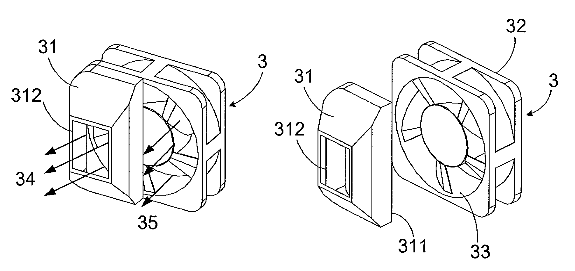
[0011]The primary objective of this invention is to provide a cooling device for use with a projection apparatus. The cooling device employs two axial fans, in which one generates an airflow partially along an airflow guiding device and then towards the interior of the light source device for cooling. The mentioned design is capable of efficiently reducing system noises and promoting the amount of airflow from the inlet of the fans to enhance cooling efficiency; Another objective of this invention is to provide a cooling device for use with a projection apparatus. By replacing the conventional blower fans with two proximate axial fans, the costs of the entire product are reduced.
[0012]Still another objective of this invention is to provide a cooling device for use with a projection apparatus. By employing an axial fan to cool the bulb in a more sufficient way, the dimensions of the other axial fan can be diminished, whereby the final products are miniaturized.
[0013]Yet a further objective of this invention is to provide a cooling device for use with a projection apparatus. By employing the airflow guiding device and partially guiding airflows along the outer end of the second axial fan to cool the bulb, the remaining airflows that are not guided towards the bulb could still cool the system. That is, the axial fan can cool the bulb as well as provide cooling airflows for the system.

Problems solved by technology

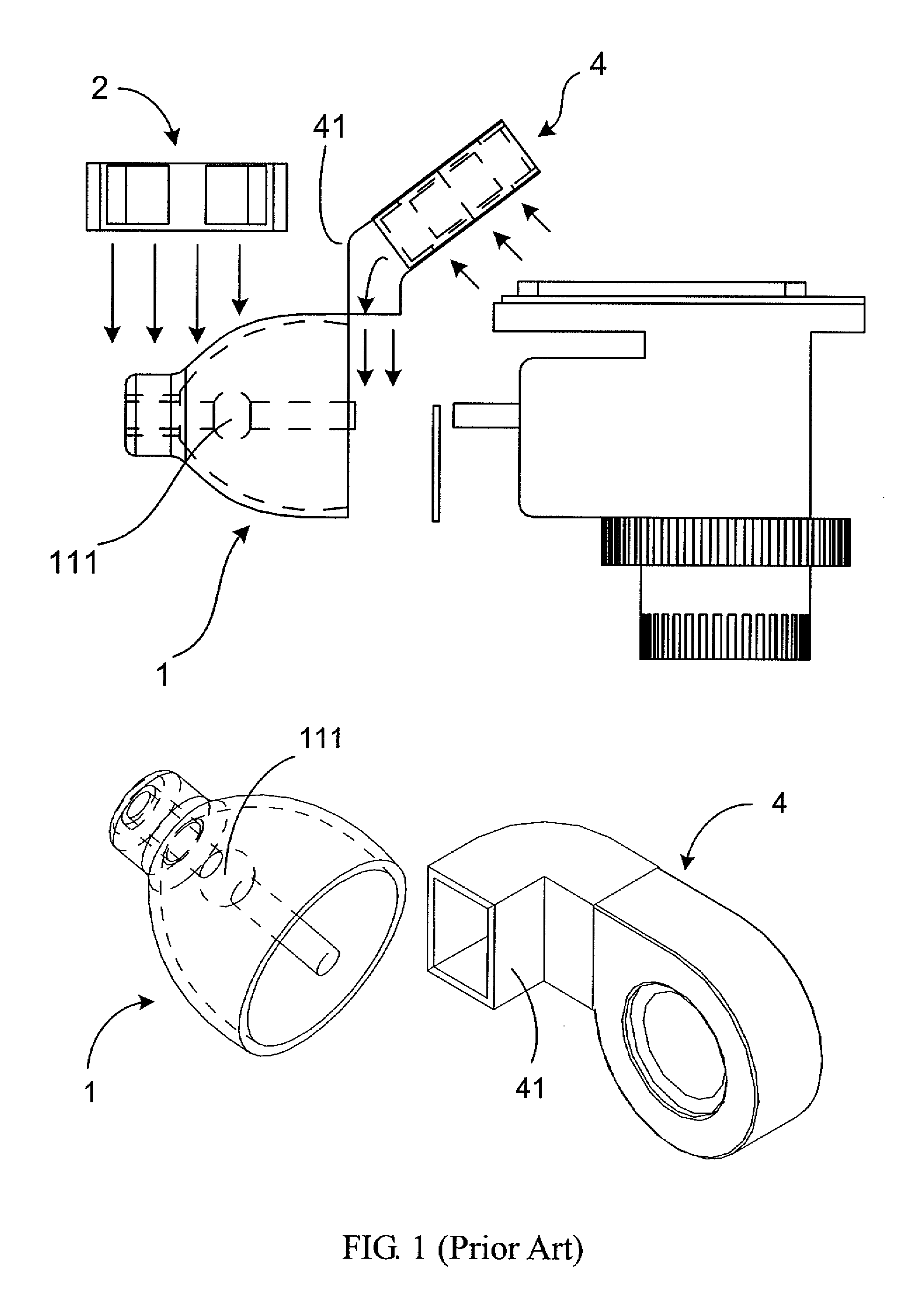
However, because the blower fan 4 is loud, the noise generating from the blower fan 4 is unfavorable under the desired amount of airflow.
As expected, the noise of the entire system increases accordingly.
Furthermore, the blower fan 4 adds an increased cost to the entire system and is only provided for cooling the bulb itself, rather than other optical elements or electrical components.

Method used


Image

  • Cooling device for use with a projection apparatus
  • Cooling device for use with a projection apparatus
  • Cooling device for use with a projection apparatus

Examples


Embodiment Construction

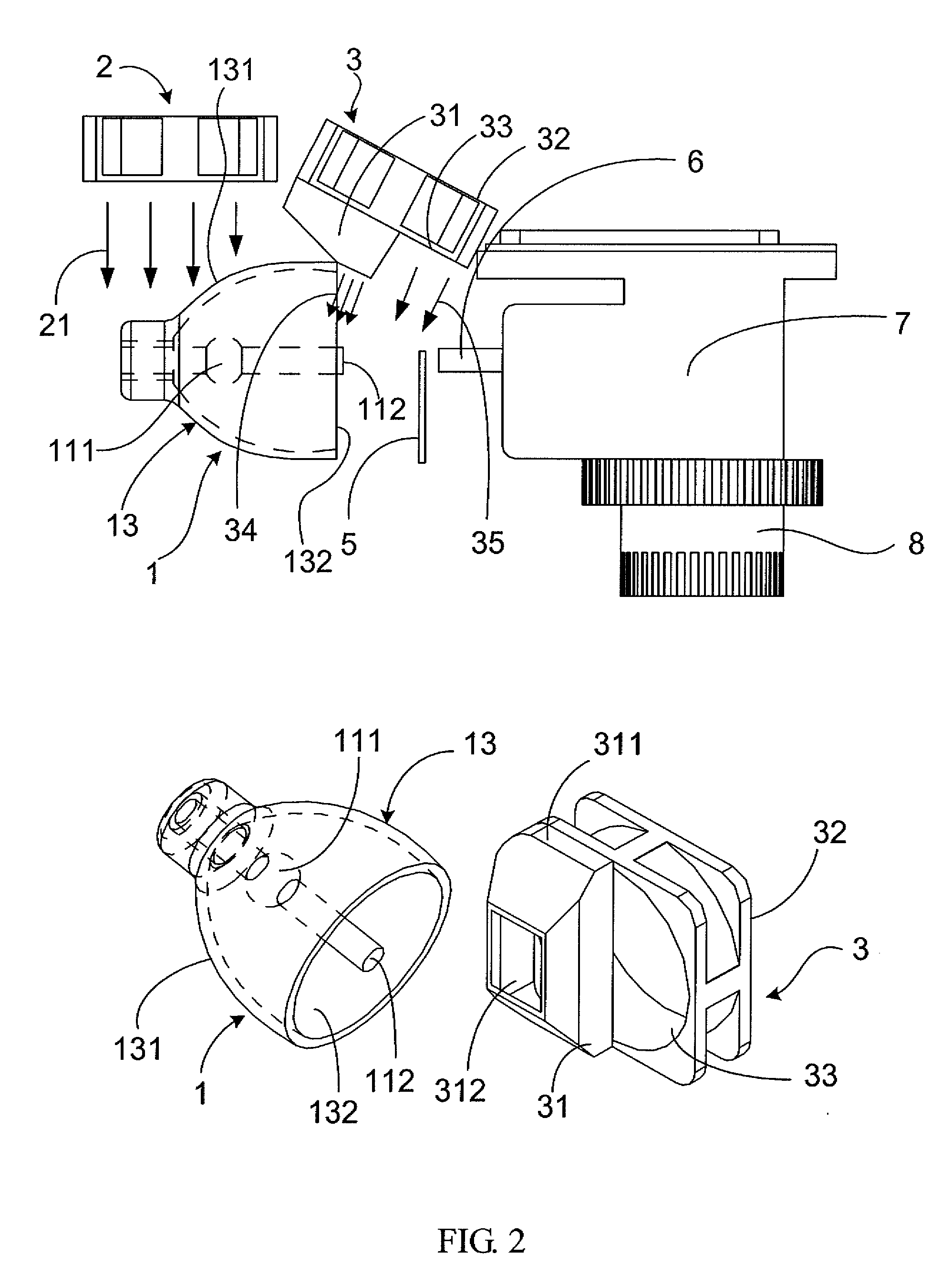
[0025]FIG. 2 is a schematic view illustrating a light source cooling device, which has two axial fans, for use with a DLP projection apparatus of the present invention. A light source device 1 is utilized to generate light beams. After traveling through the color wheel 5, the light beams are converted into different colors, for example, red (R), green (G), and blue (B). The light then travels through an integration rod 6 to be uniformed. Then, the uniform lights, handled by several optical components 7 (e.g. digital micromirror device, DMD), project outwards through the projection lens assembly 8 to form an image on the screen.

[0026]Usually, the light source device 1, for example, an illuminating lamp, is the principal heat generating component in the projection device. The lamp comprises a bulb 111, a lead wire 112, which is disposed in front of the bulb 111, and a reflector 13. The reflector 13 comprises a neck portion 131 and an opening 132. The bulb 111 is located in the neck po...


PUM


Abstract

A cooling device for use with a projection apparatus is disclosed. The cooling device includes a first axial fan and a second axial fan which is disposed adjacent to the heat generating portion of a light source device. The second axial fan comprises an inner end and an outer end disposed on the opposite side of the inner end. An airflow guiding device is disposed onto the outer end, in which the guiding device comprises an airflow outlet and an airflow inlet with an area greater than that of the airflow outlet. The airflow inlet of the guiding device shields at least a portion of the outer end of the second axial fan.

Description

[0001]This application claims priorities to Taiwan Patent Application Nos. 094146112 filed on Dec. 23, 2005, and 095118550 filed on May 25, 2006.CROSS-REFERENCES TO RELATED APPLICATIONS[0002]Not applicable.BACKGROUND OF THE INVENTION[0003]1. Field of the Invention[0004]The present invention relates to a cooling device for use with a projection apparatus. In particular, the invention relates to a light source cooling device for use with a digital light processing (DLP) projection apparatus.[0005]2. Descriptions of the Related Art[0006]Projectors have been frequently used as display equipments in offices, homes, and conference rooms. Conventional projectors can fall into two categories: liquid crystal display (LCD) projectors or digital light processing (DLP) projectors. DLP projectors apply digital projecting and displaying technologies, in which digital video signals are received and a series of digital light-pulses are generated. In addition, DLP projectors employ a DMD (digital mi...

Claims


Application Information

Patent Timeline
IPC IPC(8): G03B21/18G03B21/26
CPCG03B21/16
Inventor LIN, CHIA-JUILIN, HUI-CHIH
Owner DELTA ELECTRONICS INC
Learn More