
Recording and reproducing apparatus

a recording and reproducing technology, applied in the field of recording and reproducing apparatus, can solve the problems of page data not being recorded, page data deterioration, and difficulty in manufacturing holographic recording medium, etc., and achieve the effect of effective us

Inactive Publication Date: 2007-06-21
FUJITSU LTD
View PDF4 Cites 4 Cited by
  • Summary
  • Abstract
  • Description
  • Claims
  • Application Information

AI Technical Summary

Benefits of technology

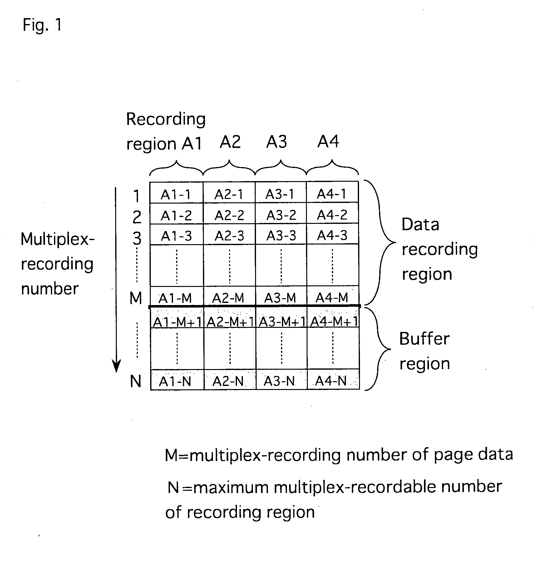
[0024] With this configuration, since the maximum multiplex-recordable number N in the recording unit region is measured and the multiplex-recording number M of the page data in one recording unit region and the multiplex-recording number (N−M) of the buffer regions which can be used as substitution regions when recording defect of the page data and the like occurs are set, the recordable space can be effectively used in each recording unit region while reliability of recording and reproducing which has been originally designed for the holographic recording medium is ensured.

Problems solved by technology

However, it is difficult to manufacture the holographic recording medium so that all recording regions have completely uniform characteristics, since a recording material for recording data in the holographic recording medium is a photosensitive material.
It is considered that such variation in recording and reproducing characteristics is caused by a problem of a manufacturing process, a physical defect which could be generated in each layer which constitutes the medium, a variation in optical characteristics due to non-uniformity of a recording and reproducing apparatus or a medium material and the like.
This is because multiplex-recording is performed by excessive exposure for the recording region having multiplex-recordable number actually smaller than the maximum recording number M beyond its recording performance, so that reproduction characteristics of the normally recorded page data could deteriorate.
In other words, the page data cannot be recorded and already recorded page data could be destroyed.
However, in this case, a yield of the medium is lowered and its manufacturing cost becomes high.
Although more page data can be recorded in the region A2, since the maximum multiplicity is set to L, the recordable space cannot be effectively used.

Method used


Image

  • Recording and reproducing apparatus
  • Recording and reproducing apparatus
  • Recording and reproducing apparatus

Examples


first embodiment

of Multiplex-Recording in the Present Invention

[0078]FIG. 1 is an explanatory diagram for angular multiplex-recording according to a first embodiment of the present invention.

[0079] Here, four recording unit regions (A1 to A4) among recordable regions of the holographic recording medium are shown. The recording unit region is referred to as the recording region simply hereinafter.

[0080] Page data is recorded in the recording region by irradiating each recording region with an information light beam and a reference light beam. In case of the angular multiplex-recording, different page data are multiplex-recorded in the same region by changing the irradiation angle of the reference light beam as shown in FIG. 13.

[0081] The recording regions (A1 to A4) in FIG. 1 are physically different recording regions and the number of page data which can be recorded in the same region (multiplex-recording number) is shown in a depth direction (vertical direction in the drawing) of the recording ...

second embodiment

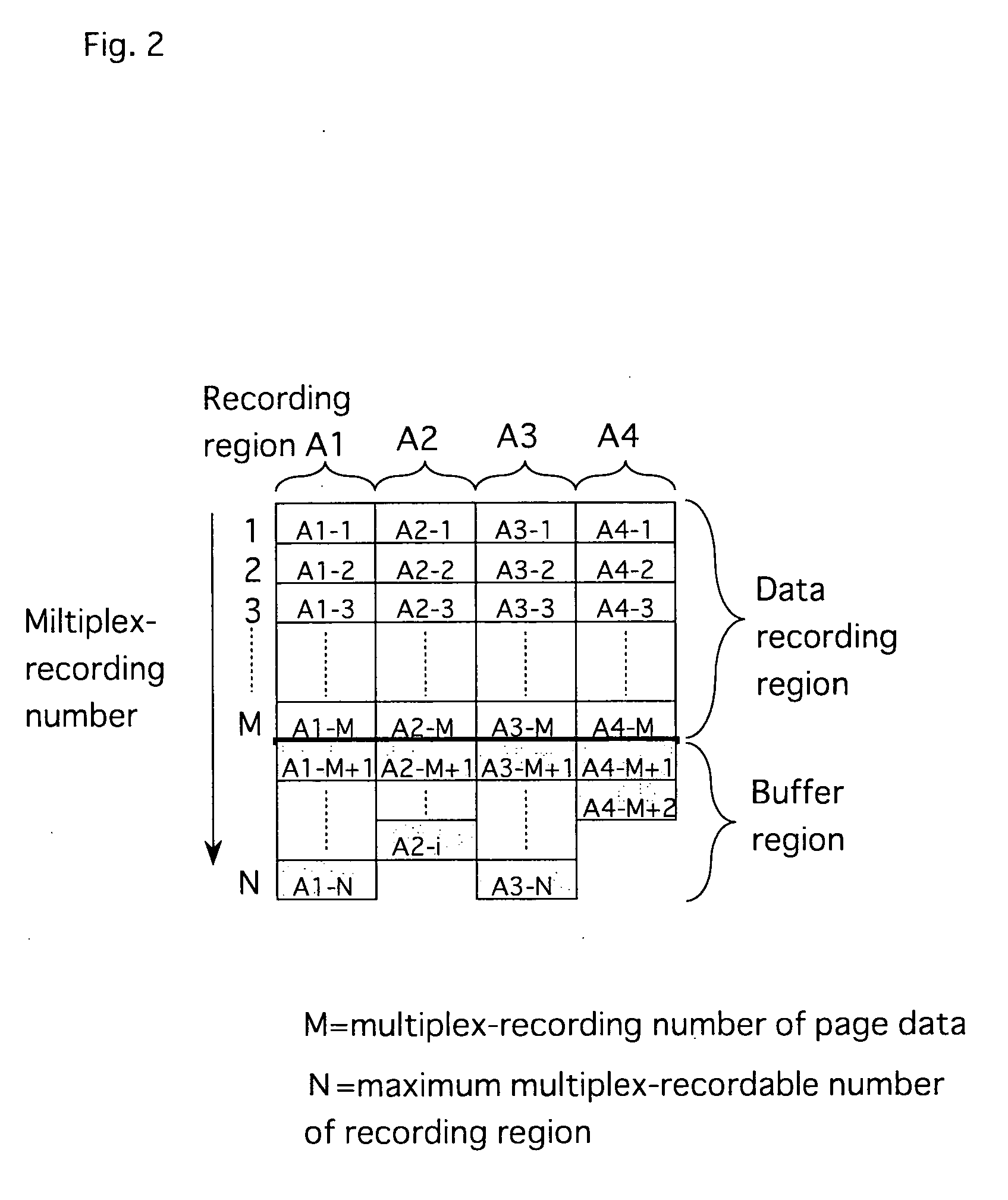
[0110]FIG. 2 is an explanatory diagram for multiplex-recording according to a second embodiment of the present invention.

[0111] Referring to FIG. 2, although the multiplex-recording number of each of the recording regions (A1 to A4) set at the time of the shipment is all M, the multiplex-recording number of the buffer regions is different. Thus, when the multiplex-recording number of the buffer regions is differentiated, the space of the recording region which can be multiplex-recorded actually can be more effectively used.

[0112] In the holographic recording medium as described above, since the recording and reproducing characteristics are different locally, there are recording regions in which the recording and reproducing can be performed more than the multiplex-recording number, and recording regions in which the originally designed multiplex-recording number M can be ensured satisfactorily but its multiplicity is not satisfactorily provided due to a physical defect. That is, t...

third embodiment

[0122]FIG. 3 is an explanatory diagram for multiplex-recording according to a third embodiment of the present invention.

[0123] Here, the multiplex-recording number of the data recording region is also variable.

[0124] For example, the multiplex-recording number of the data recording regions of a region A1 is “j” and the multiplex-recording number of the data recording regions of a region A2 is “i” (≠j).

[0125] In addition, the multiplex-recording number of the buffer regions is uniformly set to 5 in FIG. 3. However, the multiplex-recording number of the buffer regions may be different every recording region according to the characteristics of the each of the recording regions (A1 to A4).

[0126] Thus, the original multiplex-recording number j (j>M) in the recording region which has very excellent characteristics locally can be set more, so that the recording space for the page data in the recording region can be increased as compared with the case the multiplex-recording number is u...


PUM


Abstract

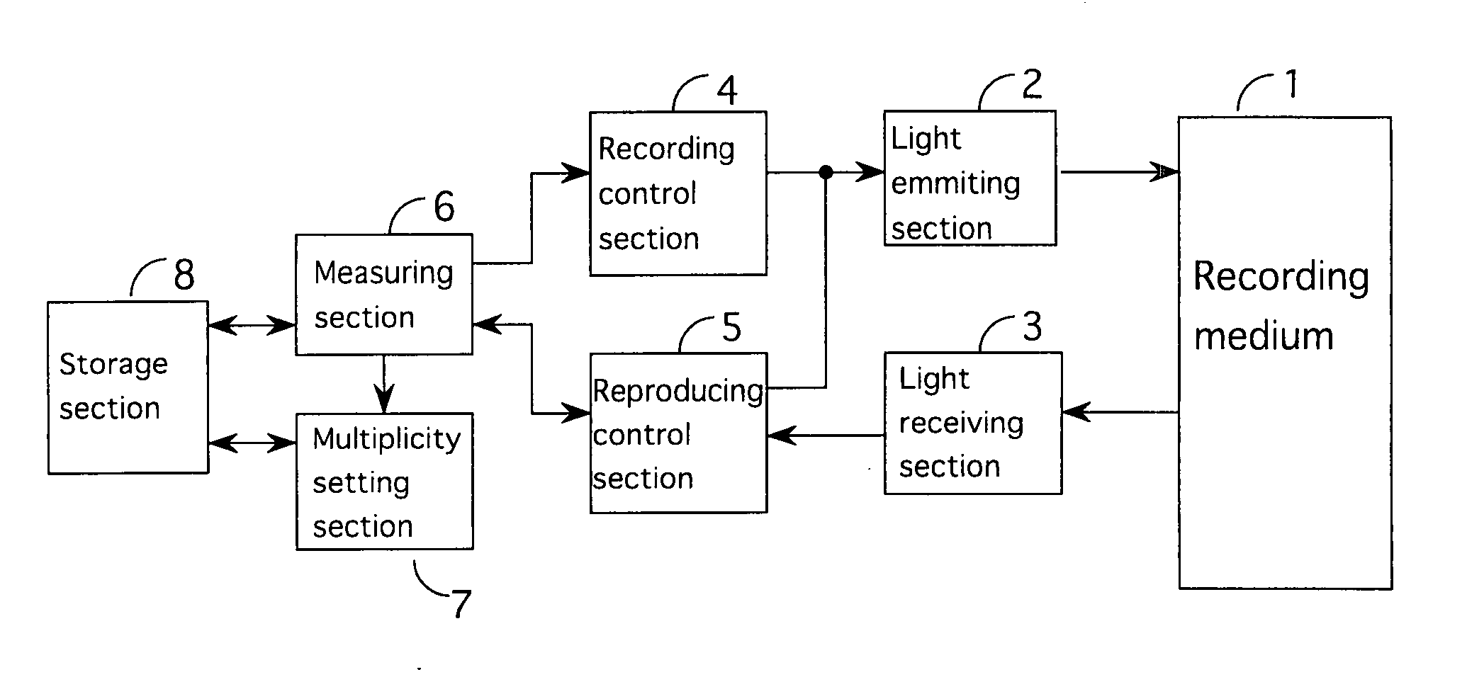
A recording and reproducing apparatus has a recording control section for multiplex-recording data in one of recording unit regions of a holographic recording medium; a reproducing control section for selectively reproducing the data multiplex-recorded in the recording unit region; a measuring section for causing specific data to be recorded in a recording unit region A to measure a maximum multiplex-recordable number N of the region A; a multiplicity setting section for setting (i) a multiplex-recording number M (M<N) of data to be recorded in the region A and (ii) a multiplex-recording number (N−M) of a buffer region of the region A, by using the maximum multiplex-recordable number N; and a storage section for storing the number N and the number M. When data B is to be recorded in the region A beyond multiplex-recording number M, the recording control section multiplex-records page data B in the buffer region of the region A within the range of the maximum multiplex-recordable number N.

Description

CROSS-REFERENCE TO RELATED APPLICATIONS [0001] This application is related to Japanese application No. 2005-319888 filed on Nov. 2, 2005, whose priority is claimed under 35 USC § 119, the disclosure of which is incorporated by reference in its entirety. BACKGROUND OF THE INVENTION [0002] 1. Field of the Invention [0003] The present invention relates to a recording and reproducing apparatus. More particularly, it relates to a recording and reproducing apparatus in which a holographic recording medium is irradiated with an information light beam and a reference light beam at the same time, and multiplex-recording of page data is performed in the same recording region in view of characteristics of the recording region. [0004] 2. Description of the Related Art [0005] On a holographic recording medium, an information light beam corresponding to two-dimensional page data and a reference light beam are irradiated in the same region of the medium at the same time, thereby recording the two-...

Claims


Application Information

Patent Timeline
IPC IPC(8): G11B7/00
CPCG03H1/28G11B7/0065G11B7/0079G11B20/1217G11B2020/1292G11B2020/1298G11B2220/2504
Inventor YAMAKAGE, YUZURUUCHIDA, AKIYOSHI
Owner FUJITSU LTD
Learn More