Eureka AIR delivers breakthrough ideas for toughest innovation challenges, trusted by R&D personnel around the world.

Low-cost disposable tourniquet cuff

a tourniquet and low-cost technology, applied in the field of pneumatic tourniquet cuffs, can solve the problems of increased pressure of tourniquets, over-all thickness and stiffness, and difficulty in uniform application of cuffs by surgical users,

Inactive Publication Date: 2007-06-14
MCEWEN JAMES A +3
View PDF47 Cites 73 Cited by
  • Summary
  • Abstract
  • Description
  • Claims
  • Application Information

AI Technical Summary

Problems solved by technology

The use of multiple layers of such materials in prior-art cuffs has increased their overall thickness and stiffness, making these cuffs difficult for a surgical user to apply consistently.
Thicker and stiffer cuffs of the prior art may also degrade performance after cuff application so that higher tourniquet pressures may be required to reliably occlude blood flow; this is undesirable because higher tourniquet pressures are associated in the surgical literature with a higher risk of patient injury.
The absence of a stiffener can lead to a reduction of the efficient application of pressure to the limb and thus can lead to an increase in the level of pressure required to stop blood flow past the cuff and into the limb.
Also, the absence of a stiffener can lead to additional stresses in the outer cuff surface due to less constrained bladder expansion.
The thick outer layer extends to all of the cuff edges, and includes an area for sealing the inner layer to the thick outer layer to form an inflatable bladder, resulting in the bladder always having a bladder width that is less than the width of the stiffener; this is undesirable because cuffs having narrower bladder widths require higher tourniquet pressures to stop blood flow, and higher tourniquet cuff pressures are associated with a higher risk of patient injury.
Also, this second type of stiffener configuration in cuffs of the prior art, in which the stiffener forms part of the inflatable bladder, greatly limits the extent to which the cuff can expand inwardly into soft tissue when the cuff is pressurized; this limitation increases the pressure required to stop or occlude blood flow in the encircled limb, especially in obese patients and patients having large amounts of soft tissue.
Further, the thick and stiff edges formed at the side edges of these prior-art cuffs may have a tendency to buckle towards the limb when the bladder is pressurized, leading to a potential soft-tissue hazard.
This reduces the effectiveness of the stiffener in directing cuff pressure toward the encircled limb across the width of the cuff, and it reduces the extent to which the cuff can expand inwardly when pressurized, thereby making its performance more sensitive to variations in application technique and thereby leading to the possible need for higher tourniquet pressures to stop blood flow past the cuff and into the limb, particularly in patients having large amounts of soft tissue and in patients with poor muscle tone.
Further, an unsecured stiffener within the cuff bladder is not as effective as a secured stiffener in helping to prevent the cuff from twisting or rolling on the limb.
In addition, to reduce the limitations of performance that are inherent in a cuff having an unsecured stiffener within the inflatable bladder, the width of the stiffener in prior art cuffs must be as close as possible to the bladder width; this can impair cuff performance and requires precise alignment of the stiffener during manufacture.
It is not desirable to attach the tie strap to the cuff surface facing the patient's limb, where such attachment may distort the cuff surface and thus lead to uneven pressure distribution and possible soft-tissue injury.
Some prior art cuffs such as Spence '304 do not include a tie strap, but such cuffs are less conveniently applied, and may result in an applied cuff that is less snug and less effective in transmitting pressure from the cuff to the limb.
Unauthorized reprocessing and reuse of such tourniquet cuffs in multiple surgical procedures may be hazardous for patients.
However, such marking on prior-art cuffs may be easily removed or obscured if the cuffs are reprocessed, leading to the possibility that surgical staff may unknowingly use disposable tourniquet cuffs that have been reprocessed in a manner not authorized by the manufacturer and hazardous to patients.
This reduces the possibility of wrinkling, pinching, bruising and other injuries to the skin and soft tissue encircled by such cuffs.
The manual labor component of cuff assembly is high, especially where multiple sewing and sealing operations are required.

Method used


Image

  • Low-cost disposable tourniquet cuff
  • Low-cost disposable tourniquet cuff
  • Low-cost disposable tourniquet cuff

Examples


Embodiment Construction

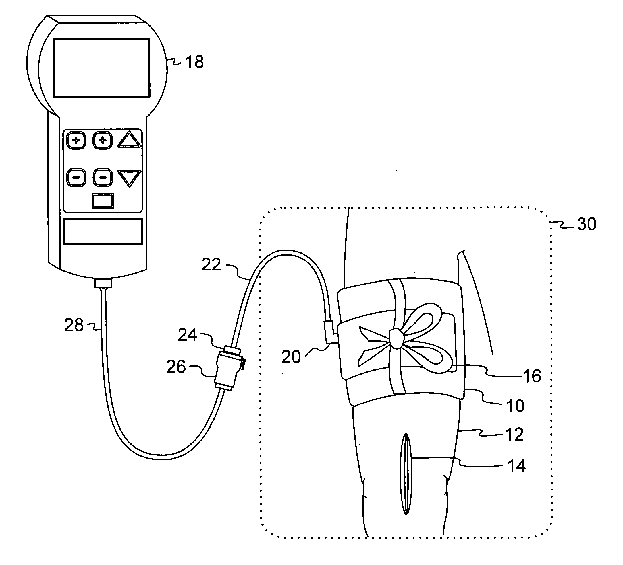
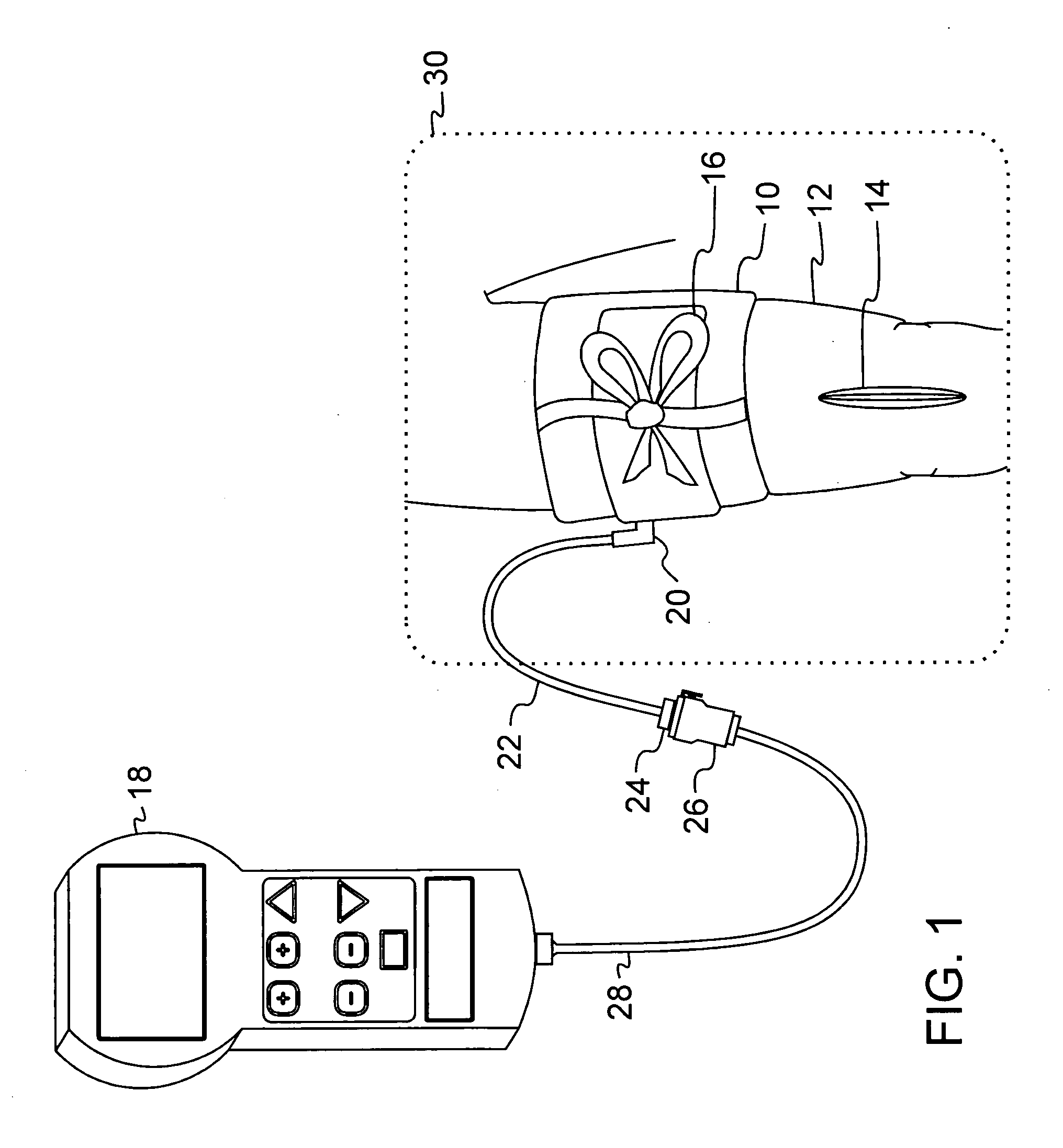
[0024]FIG. 1 is a pictorial representation of the preferred embodiment in a surgical application, showing tourniquet cuff 10 secured circumferentially around patient limb 12 proximal to surgical site 14. Tie strap 16 described further below, is tied as shown in FIG. 1 to help prevent the cuff 10 from sliding proximally or distally on patient limb 12 when cuff 10 is inflated.

[0025] The inflatable portion of tourniquet cuff 10 completely encircles patient limb 12 and is pneumatically connected to tourniquet instrument 18 via cuff port 20, cuff tubing 22, cuff connector 24, instrument connector 26 and instrument tubing 28. Tourniquet instrument 18 supplies pressurized gas for the inflation of cuff 10 and is capable of inflating cuff 10 to a pressure that will occlude the flow of arterial blood in patient limb 12 distal to cuff 10.

[0026] The perimeter of a sterile surgical field 30 encloses surgical site 14, a portion of patient limb 12, tourniquet cuff 10, and a portion of cuff tubin...


PUM


Abstract

A low-cost disposable tourniquet cuff includes: a first sheet formed of flexible material that is impermeable to gas; a second sheet facing the first sheet and formed of flexible material impermeable to gas; a bladder seal joining the first sheet to the second sheet around a perimeter to form an inflatable bladder within the perimeter; port means communicating pneumatically with the bladder and releasably connectable to a tourniquet instrument; stiffener means contained within the inflatable bladder and formed of gas-impermeable material less flexible than the first sheet, wherein the stiffener means has a stiffener width dimension less than the bladder width dimension and is joined to the first sheet to form a non-inflatable portion of the first sheet; and securing means attached to the non-inflatable portion of the first sheet and adapted to allow a surgical user to releasably secure the cuff around the limb at the desired location so that the bladder overlaps upon itself.

Description

[0001] This is a continuation-in-part of U.S. patent application Ser. No. 11 / 304,363, filed Dec. 14, 2005.FIELD OF THE INVENTION [0002] This invention pertains to pneumatic tourniquet cuffs commonly used for stopping arterial blood flow into a portion of a surgical patient's limb to facilitate the performance of a surgical procedure, and for facilitating intravenous regional anesthesia. BACKGROUND OF THE INVENTION [0003] Typical surgical tourniquet systems of the prior art include a tourniquet cuff which encircles the limb of a surgical patient and a tourniquet instrument which is releasably connected to an inflatable bladder within the tourniquet cuff through a length of tubing, thereby establishing a gas-tight passageway between the cuff and the tourniquet instrument. The tourniquet instrument contains a pressurized gas source which is used to inflate and regulate the pressure in the tourniquet cuff above a minimum pressure required to stop arterial blood flow distal to the cuff, ...

Claims


Application Information

Patent Timeline
Patent Type & Authority Applications(United States)
IPC IPC(8): A61B17/00
CPCA61B17/1322Y10T156/10A61B2017/0023A61B17/135
Inventor MCEWEN, JAMES A.JAMESON, MICHAELGLINZ, KENNETH L.UPWARD, ALLEN J.
Owner MCEWEN JAMES A
Why Eureka
Eureka Blog
Learn More