
Vital sign monitor utilizing historic patient data

a technology of vital signs and patient data, applied in the field of vital signs monitors, can solve the problems of increased time required to take blood pressure readings, patient discomfort, and monitors without access to historic information regarding patients, so as to optimize the blood pressure measurement cycle and eliminate the effect of pressure cuff over-inflation

Inactive Publication Date: 2007-06-07
GENERAL ELECTRIC CO
View PDF24 Cites 52 Cited by
  • Summary
  • Abstract
  • Description
  • Claims
  • Application Information

AI Technical Summary

Benefits of technology

"The patent describes a method and device for monitoring a patient's vital signs using a single device. The device includes a blood pressure monitor that can automatically inflate and deflate the patient's blood pressure cuff, and detect the resulting pulses to calculate the blood pressure. The device also has a unique patient identification system that communicates with a database of historical patient data, which the device uses to optimize the measurement process based on the patient's characteristics. The device can adjust the initial inflation pressure of the blood pressure cuff based on the patient's previous measurements, and can also adjust other features of the vital signs monitor based on the patient's demographic data. The device can update the patient's medical records with the current vital signs readings. Overall, the device provides a more accurate and efficient way to monitor patient vital signs."

Problems solved by technology

Since the vital sign monitor is used with multiple patients, the monitor does not have access to any historic information regarding the patient.
The over-inflation of the blood pressure cuff results in both patient discomfort and an increased amount of time required to take a blood pressure reading for the patient.
When the vital sign monitor is utilized with multiple patients, it is also difficult to provide alarm limits for the vital signs being obtained from each patient, since historic data for each of the patients is not readily available without the medical personnel consulting historic data charts at the patient's location.

Method used


Image

  • Vital sign monitor utilizing historic patient data
  • Vital sign monitor utilizing historic patient data
  • Vital sign monitor utilizing historic patient data

Examples


Embodiment Construction

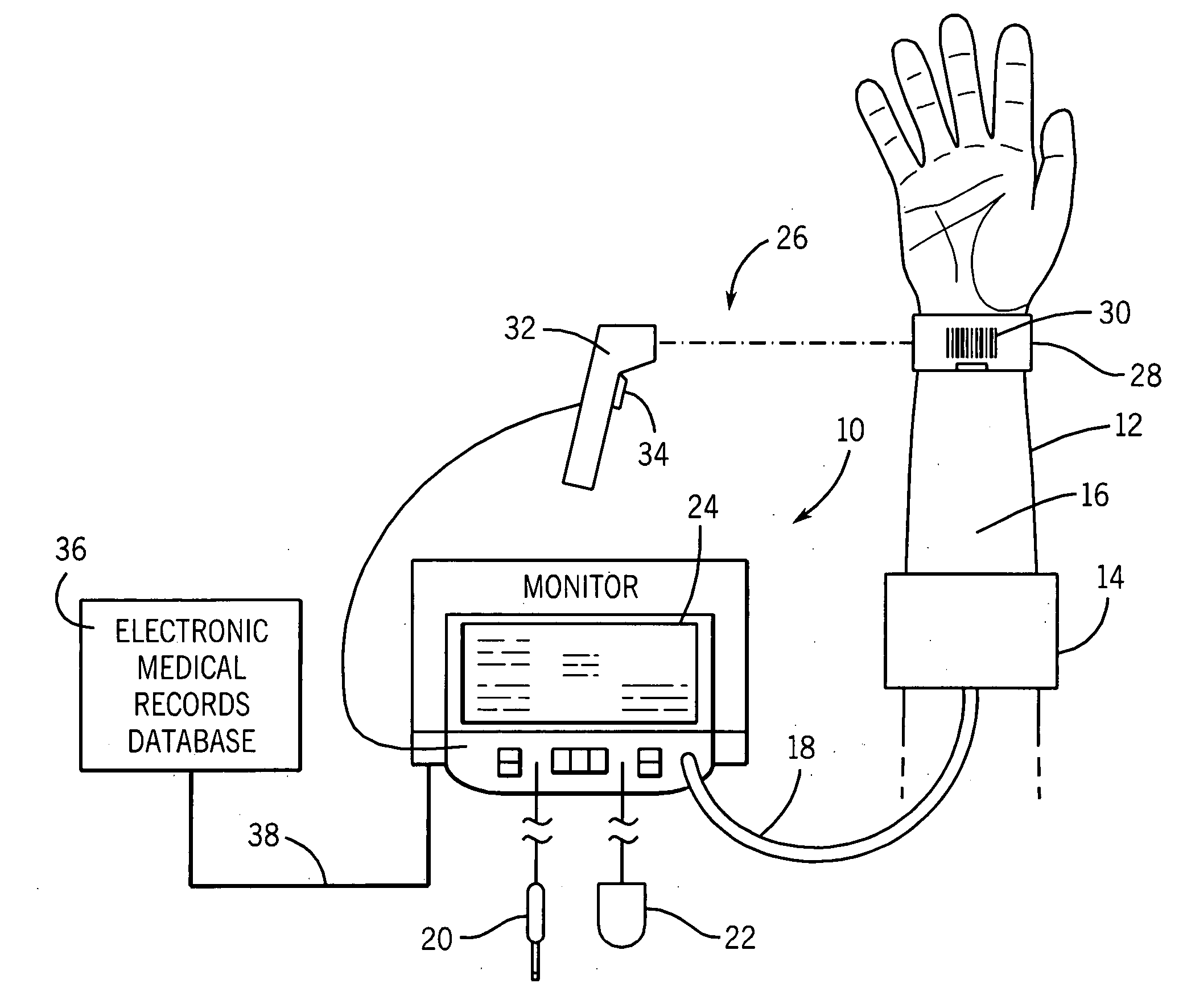
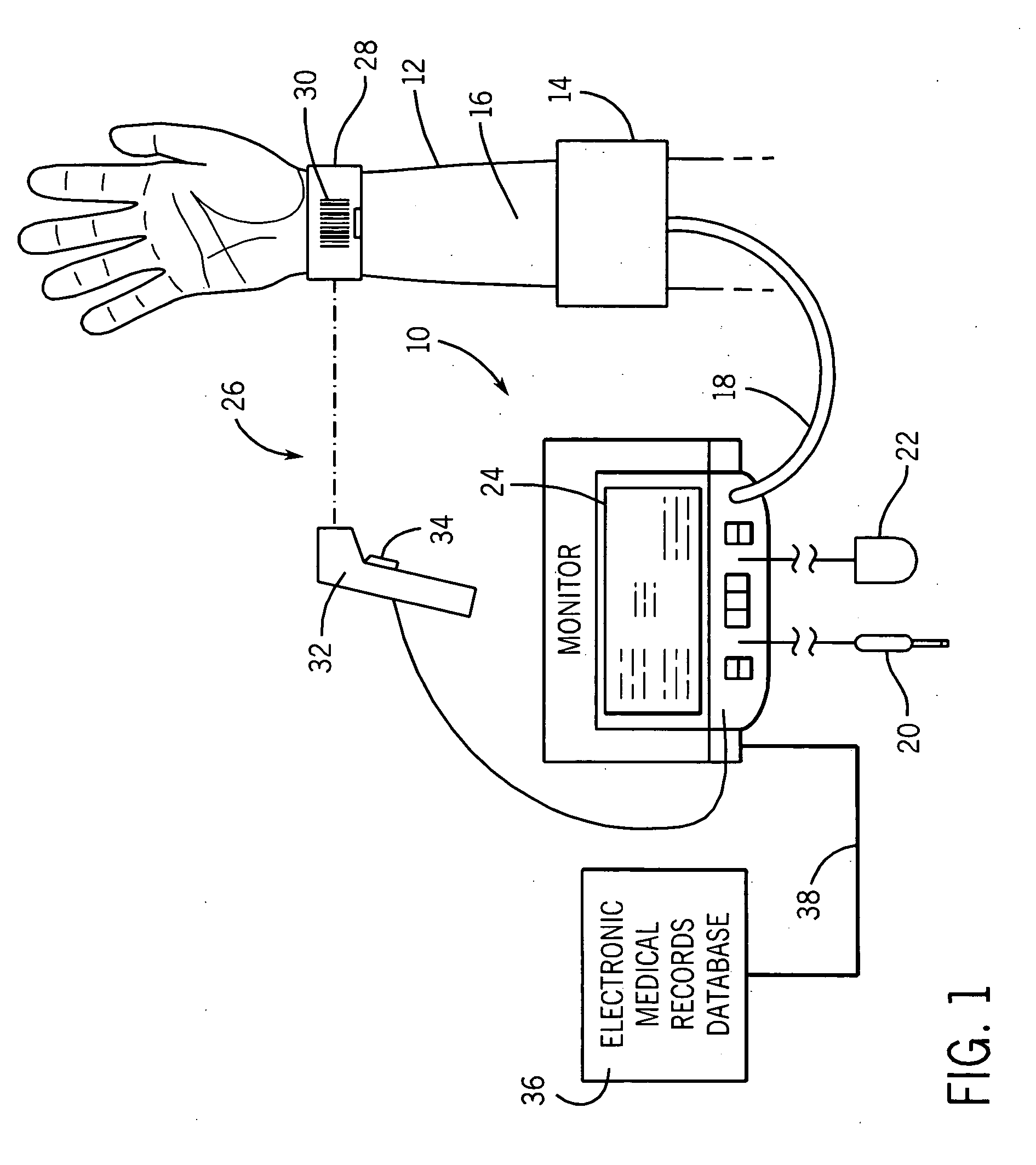
[0019] In the embodiment of the invention described in detail below, an apparatus, system and method for collecting vital sign information from a plurality of patients is provided. It should be understood that the drawings and specification are to be considered an exemplification of the principles of the invention, which is more particularly defined in the appended claims. For example, although specific embodiments of the blood pressure cuff and vital sign monitor including non-invasive blood pressure monitoring capabilities are depicted in the figures, it will be recognized that different vital sign monitoring equipment can be utilized while employing the principles of the present invention. In addition, although the figures depict particular steps related to the method of the invention, it will be recognized that alternative, equivalent steps or procedures may be employed within the principles of the claimed invention.

[0020] Referring first to FIG. 1, a vital sign monitor 10 is s...


PUM


Abstract

A vital sign monitoring system that can be used with multiple patients and utilizes historic patient data information for the patient to optimize the process of obtaining current vital sign measurements. Each patient is identified with a unique patient identification device that is automatically detected by the vital sign monitor. The vital sign monitor communicates with a medical records database and obtains historic patient data information for the patient identified by the patient identification device. The historic patient data information can be utilized by the vital sign monitor to set alarm limits for the vital sign measurements and automatically control the operation of an NIBP monitor for the specific patient.

Description

BACKGROUND OF THE INVENTION [0001] The present invention generally relates to a vital sign monitor that can be used for collecting vital sign measurements, including non-invasive blood pressure readings, from one or more patients. More specifically, the present invention relates to a vital sign monitor that can obtain historic patient data measurements for each patient and optimize the operation of the vital sign monitor based upon the historic measurements. [0002] Blood pressure is a vital sign that is typically measured on patients in medical settings. Blood pressure readings are most often taken using non-invasive blood pressure cuffs attached to the upper arm of the patient. The cuff is operatively connected to a blood pressure monitor, which receives readings from the cuff, analyzes the readings using various predetermined algorithms, and displays measurement values associated with the blood pressure of the patient. The blood pressure measurements may be taken as part of more a...

Claims


Application Information

Patent Timeline
Patent Type & Authority Applications(United States)
IPC IPC(8): A61B5/02A61B5/00
CPCA61B5/0205A61B5/02225A61B5/0225A61B5/7495
Inventor FRIEDMAN, BRUCE A.BOOTH, JOHN W.MEDERO, RICHARD
Owner GENERAL ELECTRIC CO
Learn More