
Image processing apparatus

a technology of image processing and scene detection, applied in the field of image processing apparatus detecting a scene, can solve the problem that known techniques cannot detect a scene centered on a desired subject, and achieve the effect of accurate detection

Active Publication Date: 2007-06-07
SONY CORP
View PDF11 Cites 45 Cited by
  • Summary
  • Abstract
  • Description
  • Claims
  • Application Information

AI Technical Summary

Benefits of technology

The technical effect of this patent is that it can detect specific scenes within a video or film where the viewer may be interested. This helps improve the accuracy and efficiency of identifying relevant parts of the content for further analysis and manipulation.

Problems solved by technology

The technical problem addressed in this patent is the need for techniques to allow users to easily view a specific scene in a moving image captured by a digital camera or video camera. Existing techniques such as keyword searches or matching templates have limitations in accurately detecting the desired scene. The patent aims to provide an image processing apparatus that can accurately detect the scene where a targeted object appears in a moving image.

Method used


Image

  • Image processing apparatus
  • Image processing apparatus
  • Image processing apparatus

Examples


Embodiment Construction

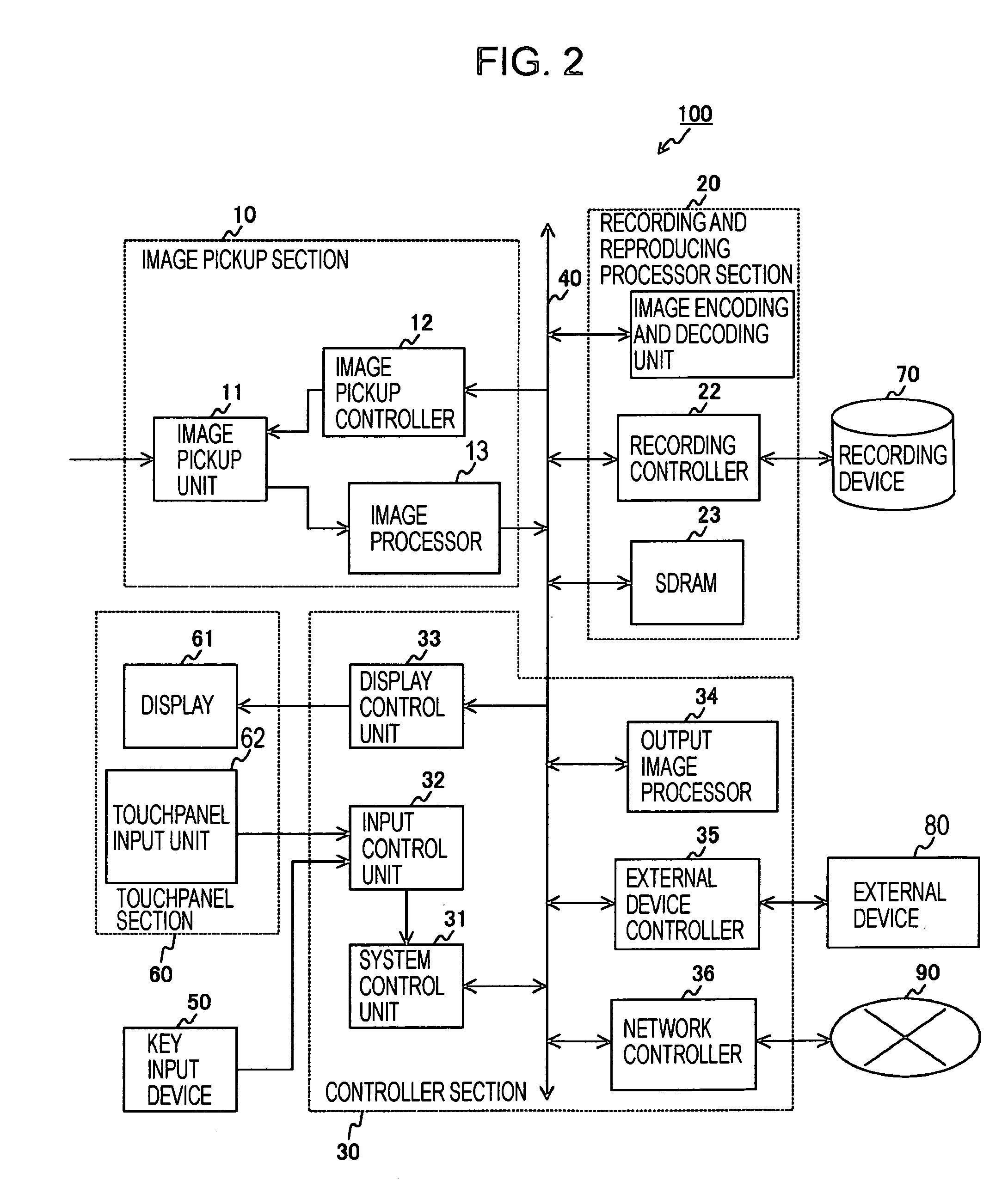
[0035] The embodiments of the present invention are described below with reference to the drawings. In the following discussion, an image pickup apparatus 100 is described as one example of an image processing apparatus.

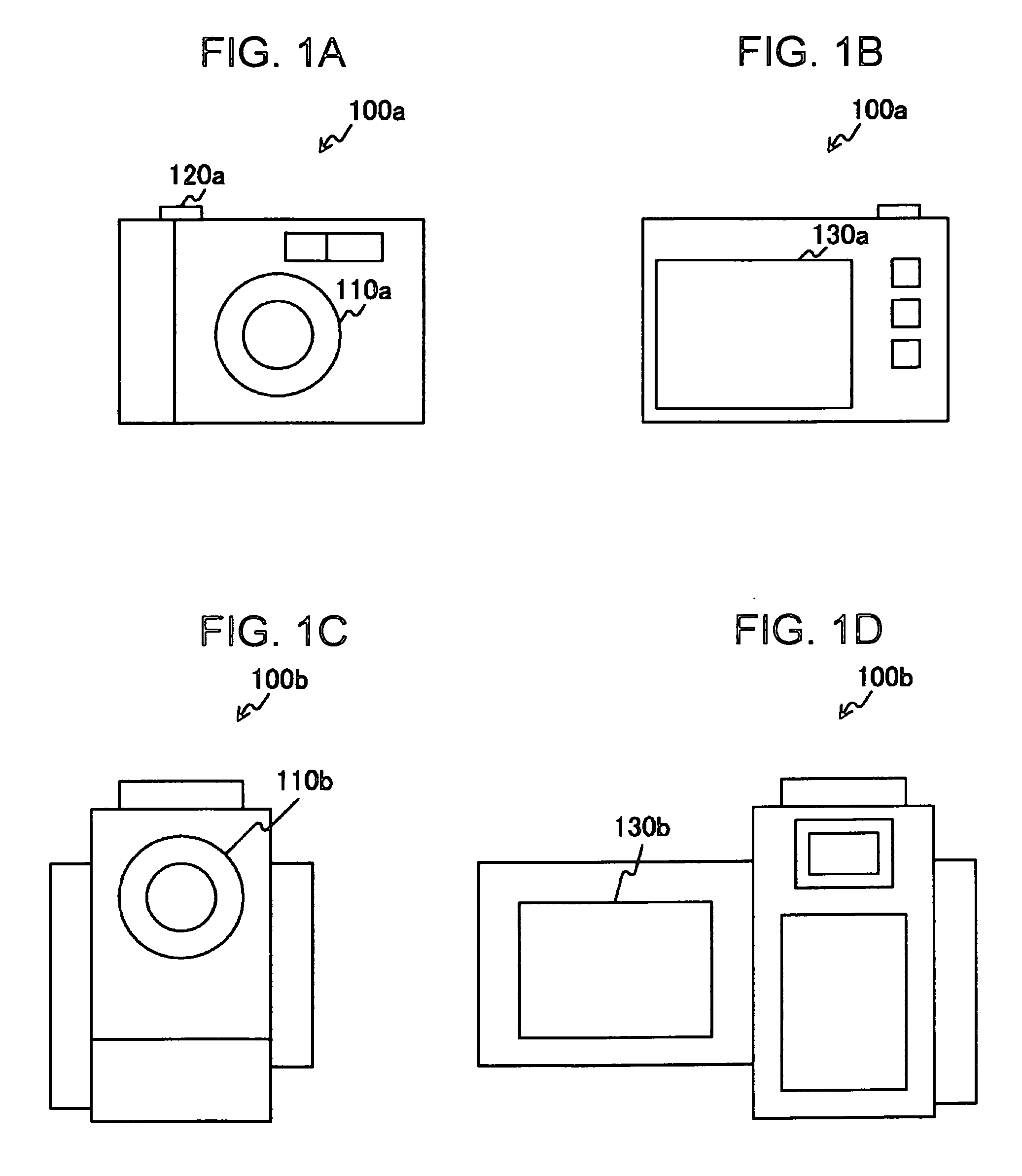
[0036]FIGS. 1A-1D are external views of image pickup apparatuses 100a and 100b as examples of the image pickup apparatus 100. The image pickup apparatus 100a is intended to mainly pick up still images, and the image pickup apparatus 100b is intended to mainly pick up moving images.

[0037]FIG. 1A is a front view of the image pickup apparatus 100a. The image pickup apparatus 100a picks up an image of a subject through a lens unit 110a. When a shutter 120a is pressed, the image pickup apparatus 100a generates a still image. FIG. 1B is a rear view of the image pickup apparatus 100a. The movement of the subject captured through the lens unit 110a is displayed on a display 130a. The generated still image is also displayed on the display 130a.

[0038]FIG. 1C is a front view...


PUM


Abstract

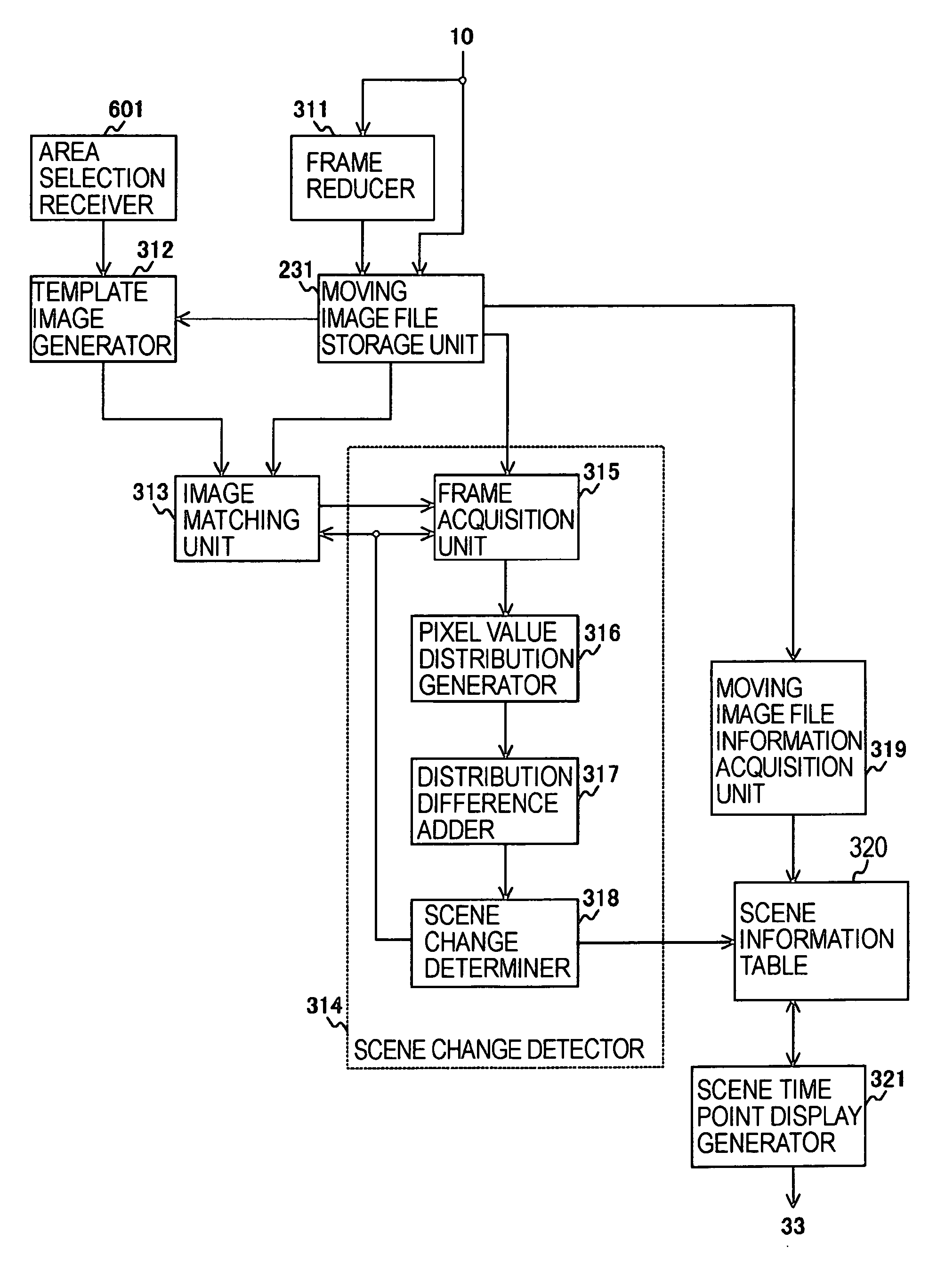
An image processing apparatus includes a moving image file storage unit operable to store a moving image file; an area selection receiving unit operable to receive a selection of a predetermined area corresponding to one of a plurality of frames forming the moving image file; a template image generating unit operable to generate as a template image an image of the selected area; an image matching unit operable to obtain the frames from the moving image file storage unit, and to match each of the frames against the template image to search for a matching frame containing an image similar to the template image; and a scene change detecting unit operable to detect a start and an end of a scene containing the matching frame.

Description


Claims


Application Information

Patent Timeline
Owner SONY CORP
Learn More