Optical disc apparatus

a technology of optical discs and optical pickups, applied in the field of optical disc apparatuses, can solve the problems of insufficient vibration-insulating effect, insufficient method of preventing or controlling vibration, and deterioration of the vibrational characteristics of the optical pickup in the focusing direction

Inactive Publication Date: 2007-06-07
HITACHI-LG DATA STORAGE +1
View PDF7 Cites 0 Cited by
  • Summary
  • Abstract
  • Description
  • Claims
  • Application Information

AI Technical Summary

Benefits of technology

[0022] As described above, any one of the optical disc apparatuses according to the present invention is effective in preventing a shift in relative position from occurring between the disc and the pickup, in suppressing the vibrational resonance of the guide shafts including the sliding base, and in preventing disc information recording / reproducing errors from occurring. Also, manufacturing processes for the conventional optical disc apparatuses can be used to realize the optical disc apparatus having the above advantageous effects, so this apparatus has an effect that it requires no additional equipment costs. In addition, this apparatus can be realized using the same material for the main guide shaft and the subsidiary guide shaft, so the apparatus has effects that it enhances reliability and that it can save materials costs.
, so this apparatus has an effect that it requires no additional equipment costs. In addition, this apparatus can be realized using the same material for the main guide shaft and the subsidiary guide shaft, so the apparatus has effects that it enhances reliability and that it can save materials costs.

Problems solved by technology

For the conventional optical disc apparatus described above in the “Background of the Invention”, however, the disclosure of the technique in Japanese Patent Laid-open No. 2000-311366, for example, does not contain information on a method of preventing or controlling the vibration of the optical pickup or the vibrational resonance of the guide shafts.
There has been, therefore, a problem in that the technique alone does not suffice to obtain a sufficient vibration-insulating effect.
This problem, in turn, causes a further problem in that the vibrational characteristics of the optical pickup in the focusing direction deteriorate under the conditions of those frequencies, and these problems are becoming increasingly prominent in recent years.

Method used


Image

  • Optical disc apparatus
  • Optical disc apparatus
  • Optical disc apparatus

Examples


first embodiment

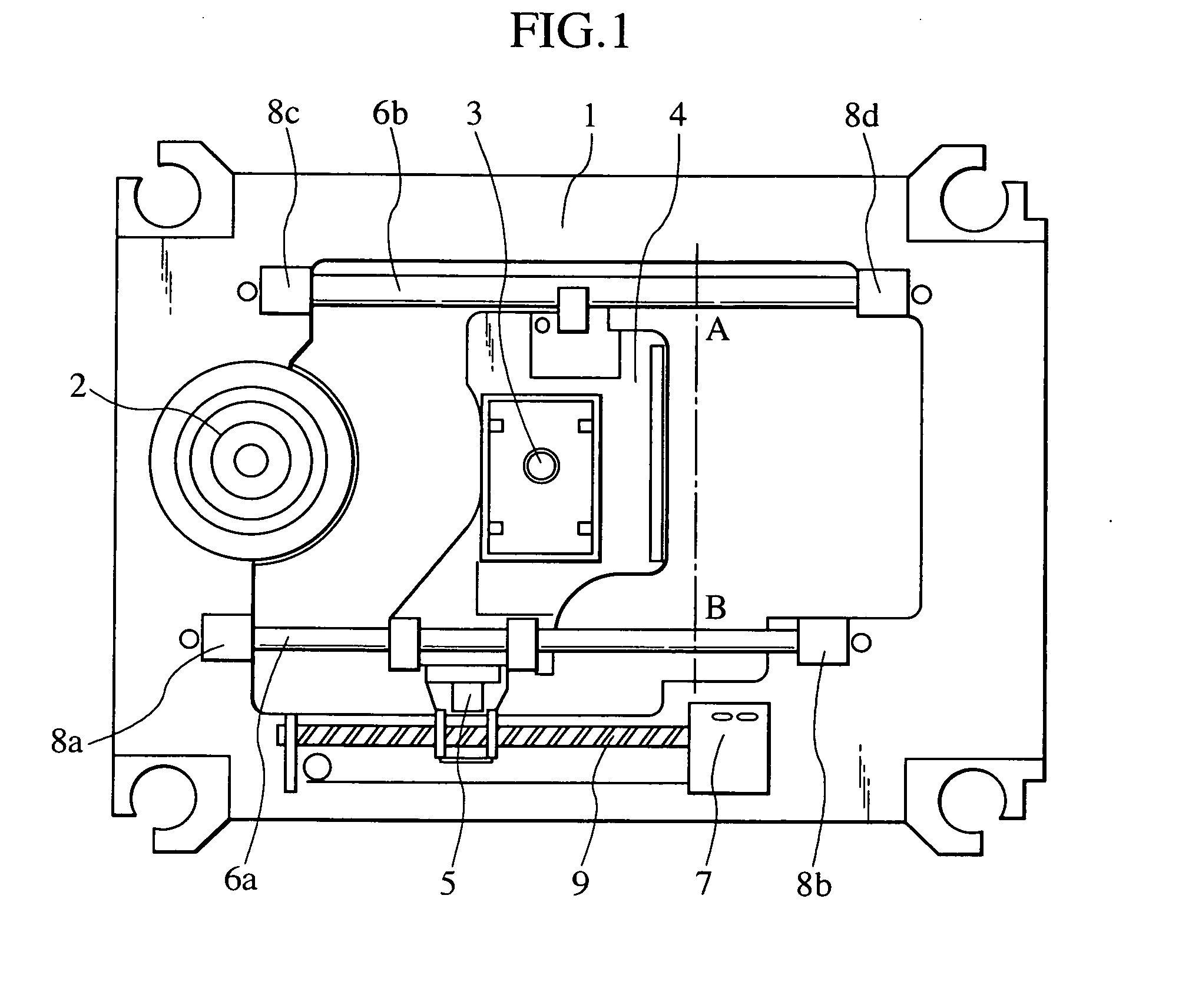
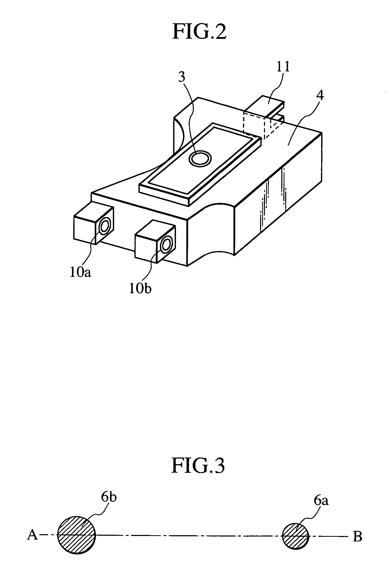
[0034]FIG. 1 is a plan view showing a total configuration of an optical disc apparatus according to a first embodiment of the present invention. The optical disc apparatus of the present embodiment in FIG. 1 includes: a chassis 1 which functions as a base material to support other constituent elements in their entirety; a spindle motor 2 for rotating an optical disc; an optical pickup 3; a sliding base 4 including the optical pickup 3; a guide rack 5 with a moving mechanism for the sliding base 4; a main guide shaft 6a which guides movement of the optical pickup 3; a subsidiary guide shaft 6b, being parallel to the main guide shaft 6a, which works together with the main guide shaft 6a to guide the movement of the optical pickup 3; a feed motor 7 which generates a driving force to move the sliding base 4; guide supports 8a, 8b which support the main guide shaft 6a in an adjusted fashion at a desired position and in a desired posture / attitude; guide supports 8c, 8d which support the s...

second embodiment

[0049] In terms of total configuration, an optical disc apparatus according to a second embodiment of the present invention is essentially the same as the optical disc apparatus of the first embodiment, shown in FIG. 1. The optical disc apparatus according to the second embodiment, however, is characterized in that a main guide shaft 12a has a diameter greater than that of the main guide shaft 6a in the first embodiment and in that unlike the subsidiary guide shaft 6b in the first embodiment, a subsidiary guide shaft 12b is of a hollow shaft shape.

[0050]FIG. 6 is a sectional view that shows section A-B of the main guide shaft and subsidiary guide shaft in the optical disc apparatus according to the second embodiment of the present invention. As shown in FIG. 6, the optical disc apparatus of the present embodiment is constructed so that the subsidiary guide shaft 12b is hollow in cross-sectional shape and greater than the main guide shaft 12a in diameter. Constructing the apparatus ...

third embodiment

[0052]FIG. 7 is a configuration diagram showing a total configuration of an optical disc apparatus according to a third embodiment of the present invention. As shown in FIG. 7, the optical disc apparatus according to the third embodiment of the present embodiment includes a main guide shaft 13 and a subsidiary guide shaft 14 in lieu of the main guide shaft 6a and subsidiary guide shaft 6b, respectively, used in the optical disc apparatus according to the first embodiment of the present invention. The optical disc apparatus according to the third embodiment also has connectors 15 between a chassis 1 and the subsidiary guide shaft 14. Description is omitted of other sections functionally and structurally overlapping those of FIG. 1. The same kind of metallic material can be used to construct the main guide shaft 13 and the subsidiary guide shaft 14.

[0053]FIG. 8 is a sectional view that shows section C-D of the main guide shaft and subsidiary guide shaft in the optical disc apparatus ...


PUM


Abstract

An optical disc apparatus includes a main guide shaft and a subsidiary guide shaft disposed so as to guide movement of a sliding base which holds an optical pickup. The optical pickup enables information recording and reproducing operations on an optical disc. The main guide shaft and the subsidiary guide shaft are configured so as to suppress vibrational resonance caused between the main guide shaft and the subsidiary guide shaft.

Description

INCORPORATION BY REFERENCE [0001] The present application claims priority from Japanese application 2005-352554 filed on Dec. 6, 2005, the content of which is hereby incorporated by reference into this application. BACKGROUND OF THE INVENTION [0002] The present invention relates generally to optical disc apparatuses. More particularly, the invention relates to an optical disc apparatus adoptable for compact discs (CDs), digital versatile discs (DVDs), Blu-ray discs (BDs), and the like, and having a vibration insulator for preventing signal read / write errors from occurring during recording and reproduction. [0003] Conventional optical disc apparatuses have some vibration insulator for preventing signal read / write errors from occurring during recording and reproduction. [0004] For example, the types of vibration insulators employed in optical disc apparatuses for CDs, DVDs, or the like, include one in which the guide shafts themselves and support sections for supporting the guide shaf...

Claims


Application Information

Patent Timeline
IPC IPC(8): G11B7/00
CPCG11B7/08582
Inventor KATOU, YUKIOYAMAUCHI, YOSHIAKINISHIDA, IKUOTAKITA, KOUHEIKATOU, SEIICHI
Owner HITACHI-LG DATA STORAGE
Why Eureka
Try Eureka