
Method and apparatus for encoded signal mapping for multi-carrier communication

a multi-carrier communication and encoded signal technology, applied in the field of multi-carrier communication encoded signal mapping, can solve the problems of deterioration of the characteristics of the entire communication, more deterioration of the sub-carrier signal, etc., to and improve the quality of communication

Inactive Publication Date: 2007-05-31
HITACHI LTD
View PDF15 Cites 42 Cited by
  • Summary
  • Abstract
  • Description
  • Claims
  • Application Information

AI Technical Summary

Benefits of technology

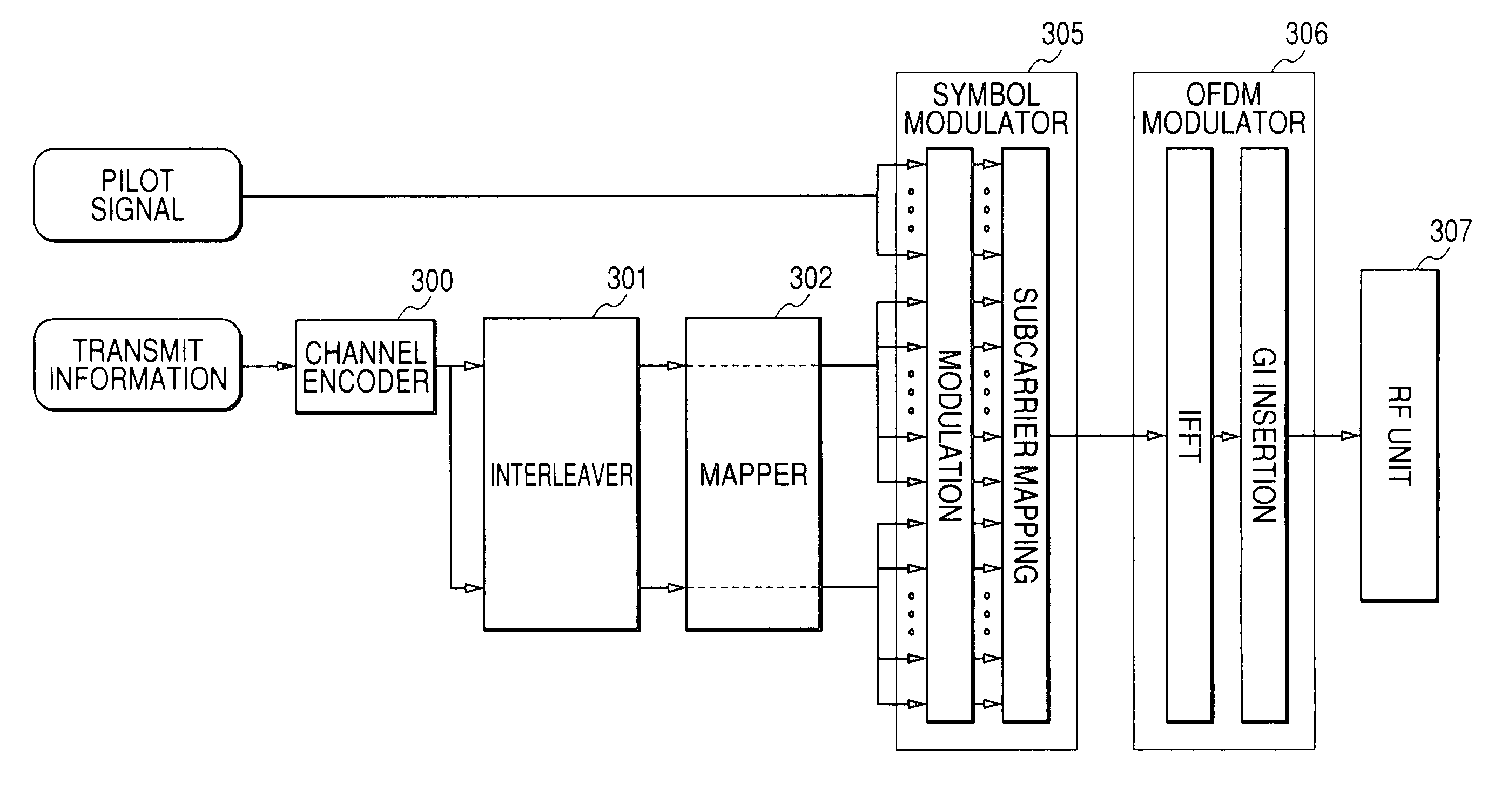
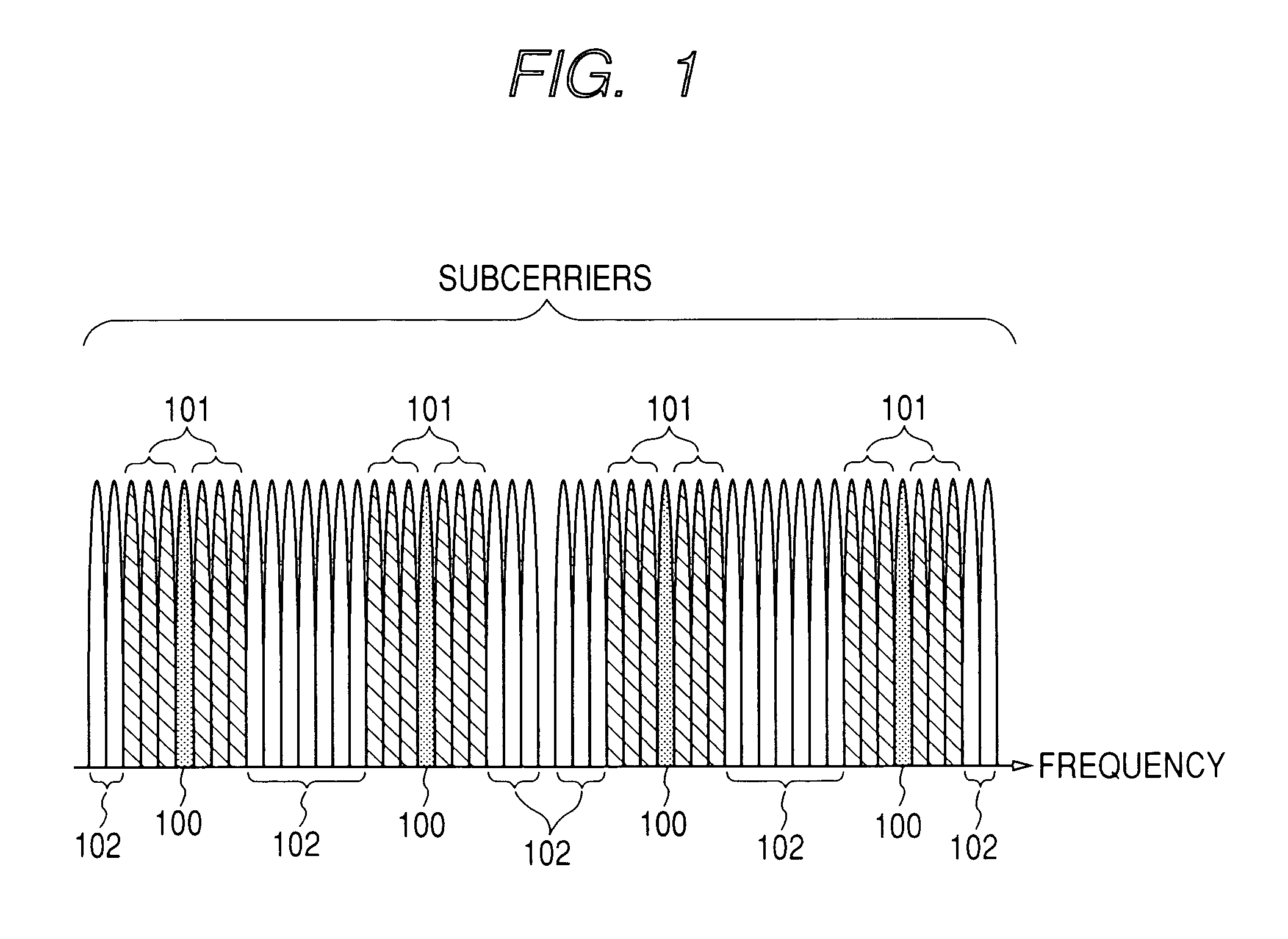
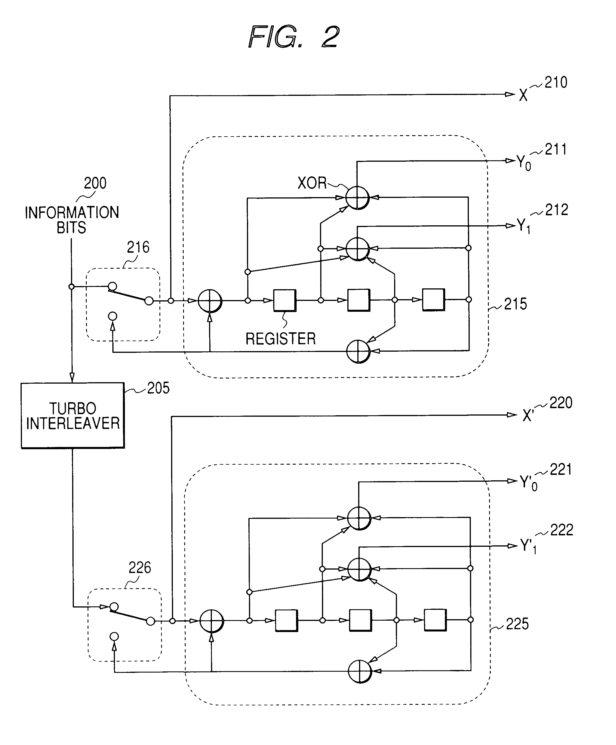
[0016] The information different in required communication quality such as systematic bits and parity bits of turbo encoded code words are combined with each other, and information that requires the higher communication quality as with the systematic bits is mapped to carriers having a frequency closer to that of carriers in which a pilot signal used as a reference signal for obtaining a phase used for demodulation exists than information as with the parity bits which do not require the higher communication quality as with the systematic bits. This makes it possible to improve the communication quality in the multi-carrier communication system such as OFDM, or simplify the signal processing.

Problems solved by technology

As a result, the signals of the sub-carriers farther not around (neighboring / adjacent to) the pilot signal are more deteriorated.
In the case where the signal whose deterioration is increased requires a high communication quality, for example, as with the systematic bits of the turbo code, and the information is low in error resistance, there arises such a problem that the characteristics of the entire communication are largely deteriorated.

Method used


Image

  • Method and apparatus for encoded signal mapping for multi-carrier communication
  • Method and apparatus for encoded signal mapping for multi-carrier communication
  • Method and apparatus for encoded signal mapping for multi-carrier communication

Examples


Embodiment Construction

[0031] Now, a description will be given in more detail of preferred embodiments of the present invention with reference to the accompanying drawings.

[0032] In the following description, a signal mapping method according to the present invention is applied to a signal that is transmitted from a first radio station to a second radio station. The first radio station is called “transmitter station”, and the second radio station is called “second radio station”. On the other hand, the signal mapping method according to the present invention can be applied to both of the transmission of a signal from the first radio station to the second radio station and the transmission of a signal from the second radio station to the first station. In this case, the first and second radio stations conduct signal processing in both of the transmitter station and the receiver station, respectively.

[0033] For example, in a system such as a cellular system or a wireless LAN of an infrastructure mode wher...


PUM


Abstract

A communication quality is improved or signal processing is simplified in a multi-carrier communication system such as OFDM. Information different in communication quality such as systematic bits and parity bits of turbo encoded code words is combined together, and information that requires a high communication quality such as the systematic bits is mapped to carriers having a frequency close to the carriers in which the pilot signal exists used as a reference phase of demodulation than the information such as the parity bits which does not require the high communication quality such as the systematic bits.

Description

CLAIM OF PRIORITY [0001] The present application claims from Japanese Application No. JP 2005-326852 filed on Nov. 11, 2005, the content of which is hereby incorporated by reference into this application. FIELD OF THE INVENTION [0002] The present invention relates to a method for mapping an encoded signal in a multi-carrier communication that occurs a quality difference in each of carriers. BACKGROUND OF THE INVENTION [0003] With wider bandwidths of a radio communication, there is used a multi-carrier communication system that divides transmit information into plural frequency bands which are called “sub-carrier” hereinafter to conduct communication. In the multi-carrier communication systems, an OFDM (orthogonal frequency division multiplexing) system uses plural frequencies that are orthogonal to each other within a symbol time range to require no guard bands between the respective sub-carriers and improve the frequency usability. As a result, the OFDM system is applied to various...

Claims


Application Information

Patent Timeline
Patent Type & Authority Applications(United States)
IPC IPC(8): H04K1/10H04W16/02H04W72/54
CPCH03M13/2957H03M13/31H03M13/356H04L1/0043H04L1/0066H04L1/007H04L1/0071H04L1/0086H04L1/009H04L25/0232H04L27/2608H04L5/0044
Inventor TAMAKI, SATOSHIYANO, TAKASHI
Owner HITACHI LTD
Learn More