
Hybrid diffuser system headloss balancing

Inactive Publication Date: 2007-05-31
EVOQUA WATER TECH LLC
View PDF18 Cites 7 Cited by
  • Summary
  • Abstract
  • Description
  • Claims
  • Application Information

AI Technical Summary

Benefits of technology

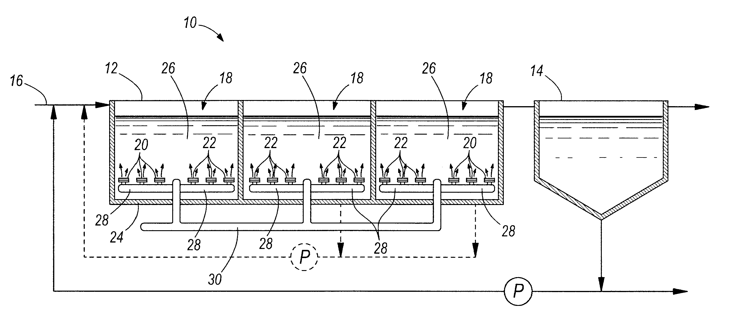
[0010] This approach is feasible because the flow imbalance through the diffuser elements is very sensitive to small differences in headloss. Therefore, it does not take much vertical correction in the position of the grid to bring the two types of grid elements into flow balance. Only a few inches of relative submersion difference is normally required to correct for the imbalance. If the characteristic headloss / air flow curves of the two types of elements have the same slope, then the resulting correction in elevation of the diffuser elements will result in substantially balanced flow distribution over a wide range of flow.

Problems solved by technology

In some applications, valves cannot be used to balance the air flow between the grid supporting the ceramic element diffusers and the grid supporting the rubber membrane diffusers.
It is known from testing that operating the diffusers for long periods of time results in headloss rise or “headloss migration” due to a change in the relative resistance to air flow through the fine bubble diffusers caused primarily by either biofouling and / or changes in water absorption of the diffuser elements.
In the design of a wastewater system it is difficult to design membrane and ceramic element diffusers to have identical headloss versus air flow curves.
Additionally, it is also difficult to maintain the headloss from element to element within manufacturing control limits and to influence or predict the different rates of headloss migration arising as a result of fouling of the diffuser elements and changes in surface properties of the rubber membrane diffusers.
It is also difficult to predict the changes over time of the flow volume into the wastewater treatment system and the operating flow rates of wastewater treated by the system as additional demands are placed on the system by growth of a community.
Because the headloss / air flow curve of a ceramic diffuser element does not match the headloss / air flow curve of a rubber membrane diffuser, changes in air flow through the headers can only truly be balanced at one flow rate.
Additionally, different rates of headloss migration over time complicate the situation further.
All of these factors prevent the engineer designing a system that may be balanced at initiation of operation of the wastewater treatment system to maintain its balance over the life of the system's operation.

Method used


Image

  • Hybrid diffuser system headloss balancing
  • Hybrid diffuser system headloss balancing
  • Hybrid diffuser system headloss balancing

Examples


Embodiment Construction

[0019] Before any embodiments of the invention are explained in detail, it is to be understood that the invention is not limited in its application to the details of construction and the arrangement of components set forth in the following description or illustrated in the following drawings. The invention is capable of other embodiments and of being practiced or of being carried out in various ways. Also, it is to be understood that the phraseology and terminology used herein is for the purpose of description and should not be regarded as limiting. The use of “including,”“comprising,” or “having” and variations thereof herein is meant to encompass the items listed thereafter and equivalents thereof as well as additional items. Unless specified or limited otherwise, the terms “mounted,”“connected,”“supported,” and “coupled” and variations thereof are used broadly and encompass both direct and indirect mountings, connections, supports, and couplings. Further, “connected” and “coupled...


PUM


Abstract

In a tank for treating wastewater and including a first plurality of air diffuser elements and a second plurality of air diffuser elements, means for adjusting the relative height of the first diffuser elements with respect to the height of the second diffuser elements in response to changing operating conditions in the tank and changes in the characteristics of the diffusers.

Description

RELATED APPLICATIONS [0001] This application claims priority to U.S. Provisional Application No. 60 / 740,758 filed Nov. 30, 2005. All of the subject matter of that provisional application is incorporated herein by reference.FIELD OF THE INVENTION [0002] The present invention relates to wastewater treatment systems and the construction to compensate for headloss migration in a wastewater treatment system using ceramic elements and membrane diffusers. BACKGROUND PRIOR ART [0003] A conventional wastewater treatment plant typically involves aeration. One type of aeration device is a fine bubble diffuser. The most common types of fine bubble diffusers are ceramic elements and rubber membrane diffusers. In some wastewater treatment systems, the systems specify the use of both ceramic element diffusers and rubber membrane diffusers in the same system. For example, ceramic elements may be installed throughout most of the treatment tanks in the wastewater treatment system and with the use of ...

Claims


Application Information

Patent Timeline
IPC IPC(8): B01F3/04
CPCC02F3/12C02F3/203Y02W10/10
Inventor LECHNER, JOHNRATZLOW, LAWRENCE B.PETIT, PETER
Owner EVOQUA WATER TECH LLC
Learn More