
Harness structure for a sliding door

a technology for harnessing and sliding doors, applied in the direction of insulated conductors, cables, coupling device connections, etc., can solve the problems of affecting the service life of the electrical power supply device 61, the difficulty of preventing slack, and the difficulty of assembling the outer sheath. to achieve the effect of preventing slack

Inactive Publication Date: 2007-05-31
YAZAKI CORP +1
View PDF2 Cites 27 Cited by
  • Summary
  • Abstract
  • Description
  • Claims
  • Application Information

AI Technical Summary

Benefits of technology

[0023] According to the above, when the sliding door is fully closed, the wiring harness from the sliding door...

Problems solved by technology

However, regarding the electric power supplying device 61 having the conventional harness structure, because expensive and complex outer sheath 66 in the form of caterpillar is used for regulating the direction of bending the wiring harness, the electric power supplying device 61 becomes expensive, heavy and time-consuming for assembling the outer sheath 66.
These problems may be happen not only the sliding door 62 of a vehicle, but also a sliding door for processing machinery or the like.

Method used


Image

  • Harness structure for a sliding door
  • Harness structure for a sliding door
  • Harness structure for a sliding door

Examples


Embodiment Construction

[0038] An embodiment of an electric power supplying device 21 having a harness structure for a sliding door will be explained with reference to Figures.

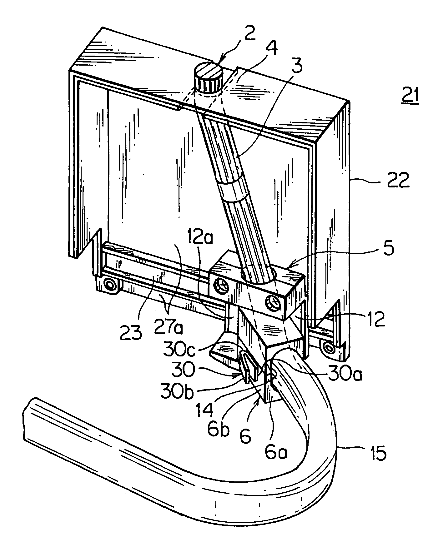
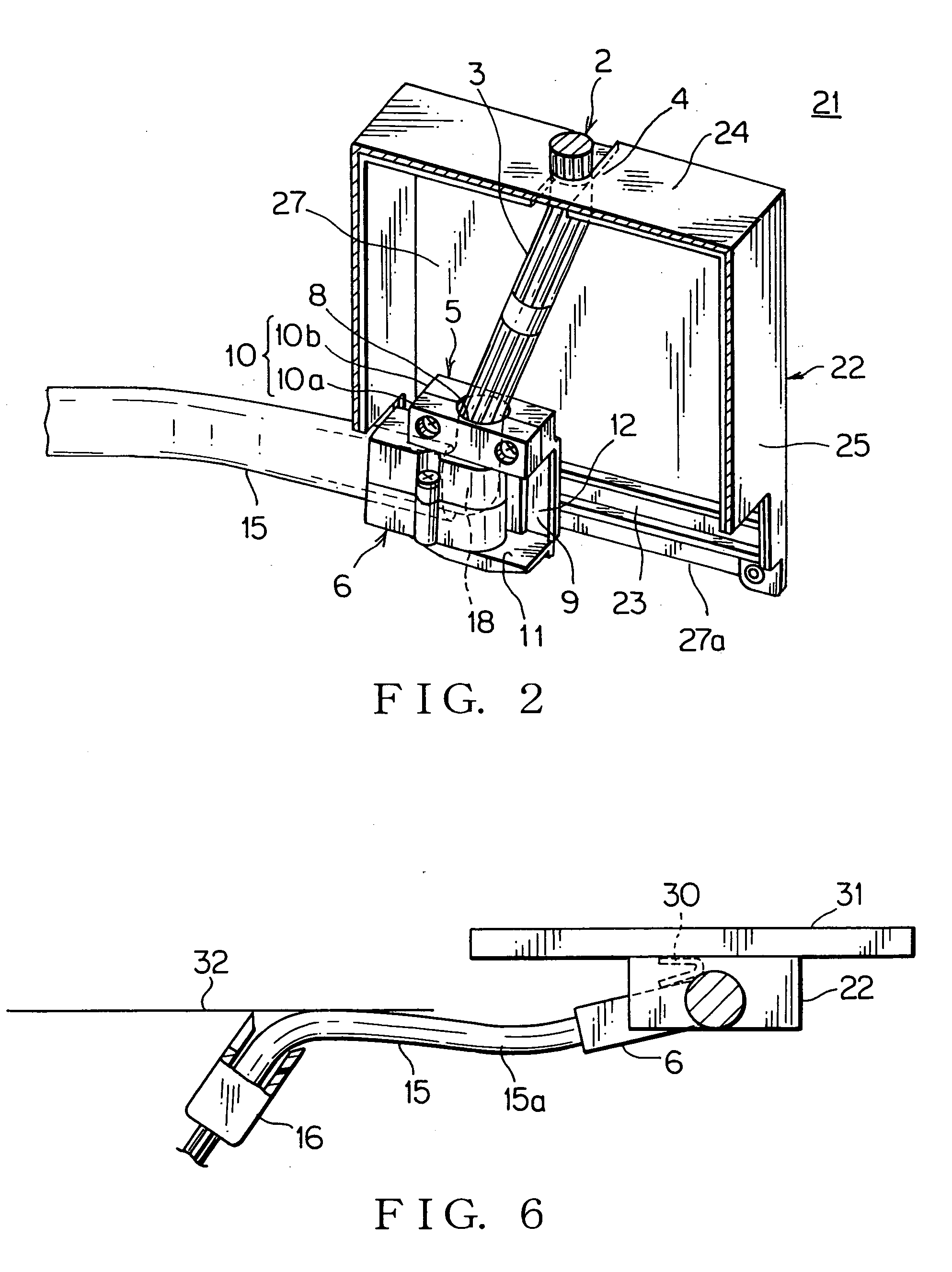
[0039] The electric power supplying device 21 includes: a case 22 swingably receiving a drooping part 3 of a wiring harness 2; a horizontal guiding rail 23 mounted on a bottom of the case 22; a slider 5 slidably engaged with the guiding rail 23; and an oscillation member 6 horizontally swingably mounted on the slider 5. The wiring harness 2 is guided from the slider 5 through the oscillation member 6 to an outside horizontally. A resilient member 30 for pressing a case side (slider 5 in this embodiment) is mounted on the oscillation member 6.

[0040] Preferably, the case 22 is made of metal or synthetic resin, the guiding rail 23 is made of metal, and the slider 5 and the oscillation member 6 are made of synthetic resin. A top end of the drooping part 3 of the wiring harness 2 is fixed to a harness fixing part 4 of a top wall 24 of t...


PUM


Abstract

A wiring harness is horizontally swingably arranged from the sliding door to a vehicle body. A resilient member arranged at the sliding door energizes the wiring harness toward the vehicle body when the sliding door is fully closed, and energizes to bend the wiring harness when the sliding door is started to be opened. The wiring harness at the sliding door is supported by an oscillation member, and the resilient member energizes the wiring harness toward the vehicle body via the oscillation member. The oscillation member is mounted on a slider, the slider is engaged with a horizontal guiding rail, and the wiring harness is arranged from the slider to the oscillation member. The wiring harness is fixed to a fastening device at the vehicle body side, and the fastening device is arranged obliquely and outwardly against a direction of closing the sliding door. When the sliding door is fully closed, the wiring harness is horizontally supported along an oblong harness guiding member at the sliding door side.

Description

CROSS REFERENCE TO RELATED APPLICATIONS [0001] This application is based on Japanese Patent Application No. 2005-340053, the contents of which are hereby incorporated by reference. BACKGROUND OF THE INVENTION [0002] 1. Field of the Invention [0003] The present invention relates to a harness structure for a sliding door. [0004] 2. Description of the Related Art [0005]FIGS. 12 and 13 show one embodiment of a electric power supplying device 61 having a conventional harness structure for a sliding door (see JP 2003-25850, A (FIGS. 2 and 4)). [0006] The electric power supplying device 61 includes: an oblong case 63 mounted on a sliding door 62 of a vehicle; a slider 64 slidably engaged with a guiding rail (not shown) of the case 63; an oscillation member 65 swingably supported by a vertical shaft of the slider in a horizontal direction; and an outer sheath 66 in a form of a caterpillar arranged bendably in substantially a U-shape inside the case and extended between the oscillation membe...

Claims


Application Information

Patent Timeline
IPC IPC(8): H02G3/04
CPCB60J5/06H02G11/006
Inventor KISU, NAOMINISHIJIMA, MASATAKA
Owner YAZAKI CORP
Learn More