
Direction finding and mapping in multipath environments

a multi-path environment and direction finding technology, applied in direction finders using radio waves, instruments, reradiation, etc., can solve the problems of limited resources available for target emitter location, relatively low signal transmitted by a target emitter, and limited time available or permissible for locating a target emitter

Active Publication Date: 2007-05-24
HERRICK TECH LAB
View PDF13 Cites 22 Cited by
  • Summary
  • Abstract
  • Description
  • Claims
  • Application Information

AI Technical Summary

Problems solved by technology

For example, the signal transmitted by a target emitter may be of relatively low power, as in the case of emergency beacons or emergency radios, or may be masked, distorted or effectively reduced by terrain or weather conditions, and such conditions may be intentionally imposed in, for example, military or otherwise hostile situations.
In addition, the time available or permissible for locating a target emitter may be limited in both military and civil situations, that is, and for example, in military counter-measures operations or in search and rescue operations, and the resources available for target emitter location may be limited.
The locator system must be capable of identifying the geographic location of a target emitter with the greatest possible accuracy as insufficient accuracy in locating a target emitter may render counter-measures ineffective in military situations and may unacceptably delay locating or reaching the target emitter in civil situations, such as search and rescue operations, particularly in difficult terrain or weather conditions.
These method of the prior art are, however, subject to significant limitations and problems.
For example, signal propagation factors between the emitter and the locator system path at various points, such as variations in propagation conditions, local multipath distortions, multiple propagation paths and reflections, will result in significant errors in the measured gradients of the wavefront and this significant errors in the measured bearings between the locator system and the target emitter.
One of if not the most significant problem in the direction finding methods of the prior art is that of multipathing, that is, the tendency for a received signal to appear to arrive from multiple sources separated from the true source.
This method is, however, historically subject to systemic errors for a number of reasons.
For example, if the antennas are spaced too closely there will be correlation between the multipath components of the received signal, and between the multipath components and the direct arrival component, resulting in an induced multipath bias error that cannot be “washed out” even by time integration of the received signal components.
If, however, the antennas are spaced too far apart, such as more than one wavelength apart, the multipath and direct arrival components will be decorrelated, but there will be phase ambiguity in the received signals because the received direct arrival component, for example, will contain more than one wavelength.

Method used


Image

  • Direction finding and mapping in multipath environments
  • Direction finding and mapping in multipath environments
  • Direction finding and mapping in multipath environments

Examples


Embodiment Construction

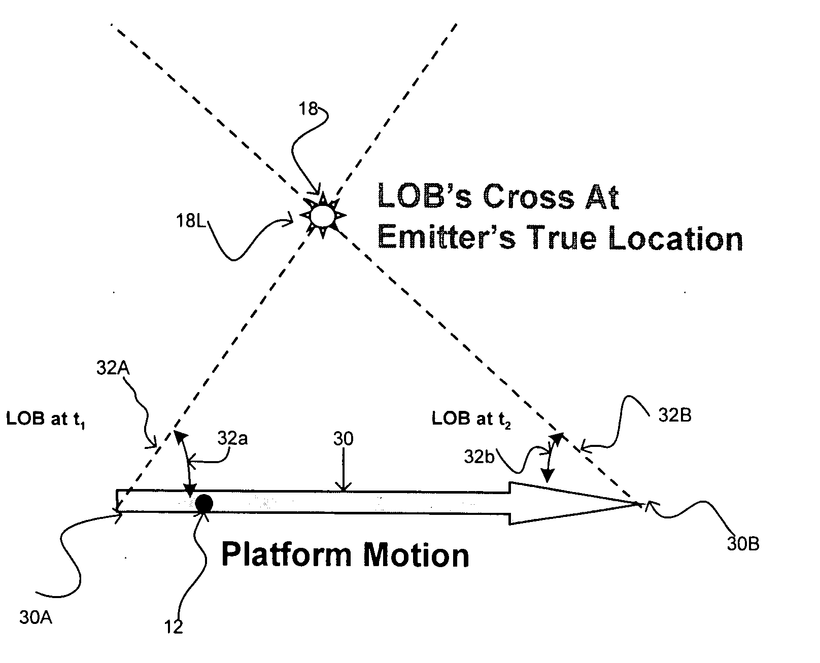
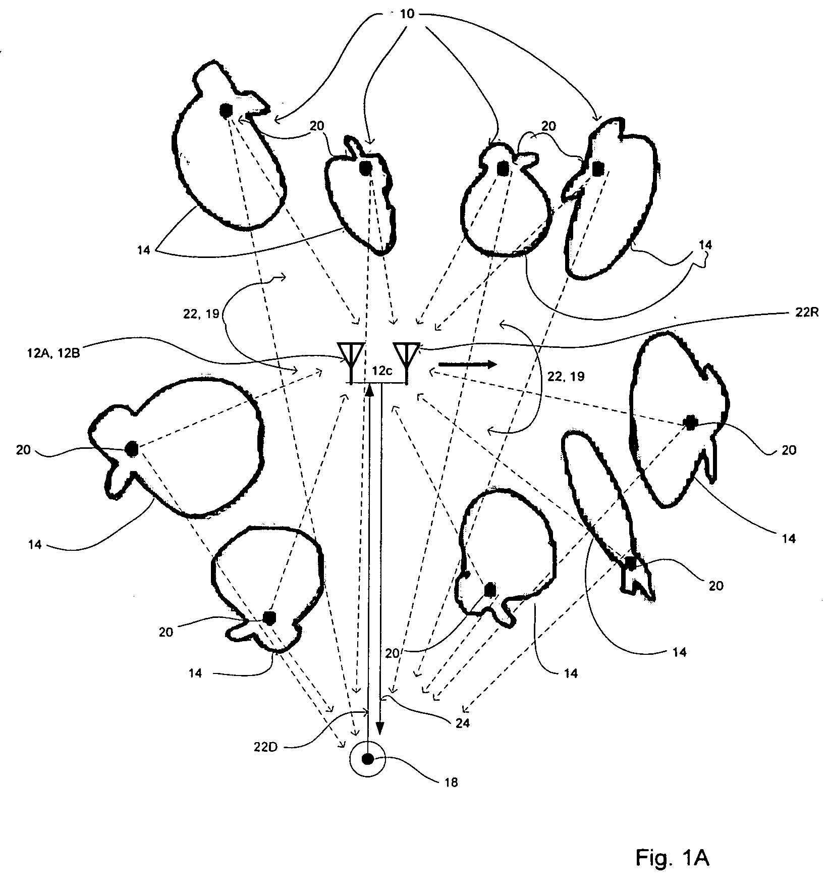
[0029] First considering multipath and the problems arising from multipath as illustrated diagrammatically in FIG. 1A, multipath sources 10 typically appear to surround the receiving unit 12 and to have effectively random radiation patterns 14 and arise from the reflection or refraction of a transmitted signal 16 from a transmitter 18 by “scatterers”20, which may be any element of the environment capable of reflecting the original signal or of refracting the original signal around themselves.

[0030] As illustrated in FIG. 1A, conventional direction finding systems typically employ two or more DF (direction finding) receiving antennas 12A and 12B spaced apart from one another along a “baseline”12C and compare the amplitudes or phases of the signals received at the DF antennas 12A and 12B to determine the direction to the transmitter 18. This method is, however, historically subject to systemic errors for a number of reasons. For example, if the DF antennas 12A and 12B are spaced too ...


PUM


Abstract

Determining the direction of a direct arrival path between a receiver and a transmitter in a multipath environment by determining a transmitter heading relative to the receiver as proportional to a frequency offset of the direct path signal component relative to a multipath pedestal, an absolute velocity of the transmitter as proportional to a width of the multipath pedestal, a relative velocity between the transmitter and the receiver as proportional to a magnitude and a direction of doppler shift of the direct arrival component of the received signal relative to the doppler pedestal, and an amplitude of the multipath pedestal as proportional to a number and magnitude of scatterers in the multipath environment. The method is applied for continuous wave and modulated signals, for stationary and moving transmitters and for tracking and mapping transmitter paths.

Description

FIELD OF THE INVENTION [0001] The present invention relates to the location of stationary and mobile transmitters by direction finding from mobile vehicles and, in particular, in a multipath environment. BACKGROUND OF THE INVENTION [0002] There are many circumstances wherein it is necessary or desirable to determine the geographic location of an emitter of electromagnetic radiation, such as a radar system, a communications facility or device or an emergency beacon or transmitter. Typical applications may include, for example, military signal intelligence (SIGINT) and electronic intelligence (ELINT) operations for locating radar or communications facilities, and air, land and sea rescue operations wherein it is necessary to locate an emergency beacon or transmitter, such as used in aircraft and vessels, or communications devices ranging from conventional or emergency radio devices to cell phones. [0003] Such applications and operations are characterized by common requirements that ar...

Claims


Application Information

Patent Timeline
IPC IPC(8): G01S5/02G01S19/11
CPCG01S3/10G01S3/46G01S5/0215G01S5/04G01S5/0218
Inventor HERRICK, DAVID L.
Owner HERRICK TECH LAB
Learn More