
Color mis-registration measurement using an infra-red color density sensor

a color density sensor and color mis-registration technology, applied in the printing arts field, can solve the problems of limiting the accuracy of manual spacing measurement, time-consuming manual approaches, waste of paper or other print media,

Inactive Publication Date: 2007-05-17
XEROX CORP
View PDF14 Cites 13 Cited by
  • Summary
  • Abstract
  • Description
  • Claims
  • Application Information

AI Technical Summary

Benefits of technology

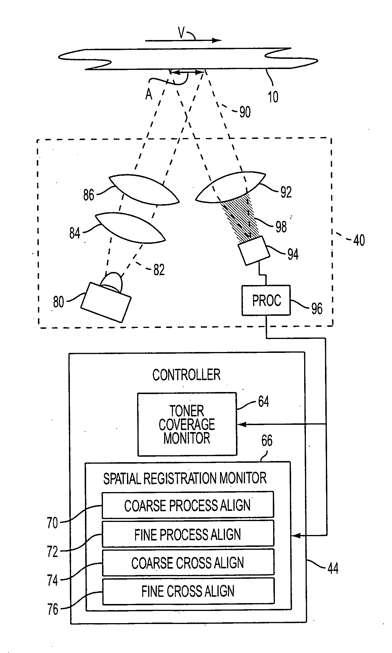
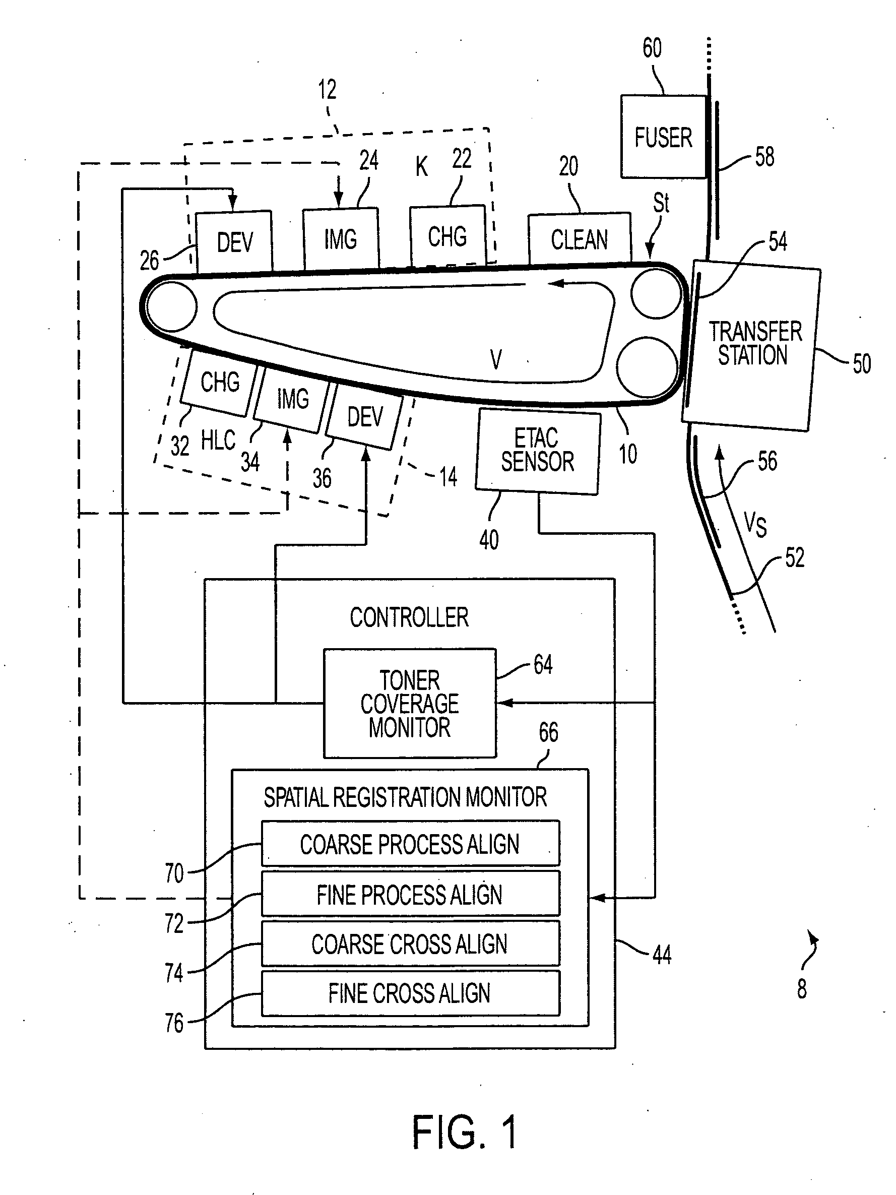
[0011] In some embodiments, a xerographic printing method includes xerographic printing performed using a moving photoreceptor and multiple toner development systems. A pattern of toner-coated regions is formed on the moving photoreceptor using two or more toner development systems of the multiple toner development systems. The pattern includes alternating toner coated regions each large enough to substantially fill the sensor area of the toner density sensor. The toner coated regions alternate along a direction of photoreceptor movement. The pattern of toner-coated regions is measured using a toner density sensor as the moving photoreceptor moves the pattern of toner-coated regions through a sensor area of the toner density sensor. The misregistration is determined based on a time varying signal of the toner density sensor produced as the photoreceptor movement transitions the measuring across the alternating toner-coated regions.

Problems solved by technology

Such manual approaches are time-consuming, waste paper or other print media, and are not amenable to rapid periodic registration calibration during printing.
Moreover, intervening processes such as toner spreading during the fusing can limit the accuracy of the manual spacing measurements used for the manual registration process.
The dedicated MOB sensor and timing-based alignment process substantially increases printing system cost and complexity.
This approach again involves a dedicated sensor, thus increasing printing system cost and complexity.

Method used


Image

  • Color mis-registration measurement using an infra-red color density sensor
  • Color mis-registration measurement using an infra-red color density sensor
  • Color mis-registration measurement using an infra-red color density sensor

Examples


Embodiment Construction

[0020] With reference to FIG. 1, a xerographic printing system 8 includes a photoreceptor in the form of a moving photoreceptor belt 10 driven by gears, pulleys, or so forth in a direction v that is counterclockwise in the viewing direction of FIG. 1. The illustrated example xerographic printing system 8 includes two toner development systems: a main black (K) toner development system 12, and a secondary highlighting color (HLC) toner development system 14. While the example printing system includes two toner development systems 12, 14, it is to be appreciated that the spatial registration and toner coverage measurement and calibration techniques described herein are readily applied to printing systems with three, four, or more toner development systems. For example, the spatial registration and toner coverage measurement and calibration techniques described herein are readily applied to CMYK color printers having four toner development systems. Moreover, the example photoreceptor 1...


PUM


Abstract

A xerographic system (8) includes a moving photoreceptor (10) and multiple toner development systems (12, 14) arranged to selectively dispose regions of toner on the moving photoreceptor. A toner density sensor (40) is arranged to measure toner density on the moving photoreceptor over a sensor area (A). A toner coverage monitor (64) operatively connected with the toner density sensor (40) monitors toner coverage based on measurements by the toner density sensor of toner coverage calibration regions disposed on the moving photoreceptor by the multiple toner development systems. A spatial registration monitor (66) also operatively connected with the toner density sensor (40) monitors spatial registration of the multiple toner development systems based on measurements by the toner density sensor of spatial registration calibration regions disposed on the moving photoreceptor by the multiple toner development systems.

Description

BACKGROUND [0001] The following relates to the printing arts. It finds particular application in spatial alignment of highlight and black toner development systems in black xerographic printing with highlighting, and is described with particular reference thereto. The following finds more general application in spatial alignment of xerographic marks produced by different toner development systems such as are used in full color xerographic printing, two-tone xerographic printing, and so forth. [0002] In xerographic printing employing a single toner development system, a moving photoreceptor belt passes through a charging station where it is electrostatically charged. The electrostatically charged belt then passes through an imaging station where an electrostatic image is formed on a portion of the belt by selectively discharging regions of the photoreceptor belt to form a latent image. The selective discharging is typically performed by selective exposure to visible, infrared, ultrav...

Claims


Application Information

Patent Timeline
Patent Type & Authority Applications(United States)
IPC IPC(8): G03G15/00G03G15/01
CPCG03G2215/00042G03G2215/0161G03G2215/017G03G15/5041
Inventor BONINO, PAUL S.SHOEMAKER, RALPH A.MARTIN, MICHAEL J.
Owner XEROX CORP
Learn More