
Camera accessory and camera

a technology for accessories and cameras, applied in the field of camera accessories and cameras, can solve problems such as inconvenient operation, and achieve the effects of saving user's labor, preventing wasteful consumption of battery power, and simplifying the operation of illumination

Inactive Publication Date: 2007-05-17
FUJIFILM CORP
View PDF10 Cites 1 Cited by
  • Summary
  • Abstract
  • Description
  • Claims
  • Application Information

AI Technical Summary

Benefits of technology

[0005] An object of the present invention is to provide a camera accessory and a camera that enable to easily and securely operate an operating portion even under a dark environment.
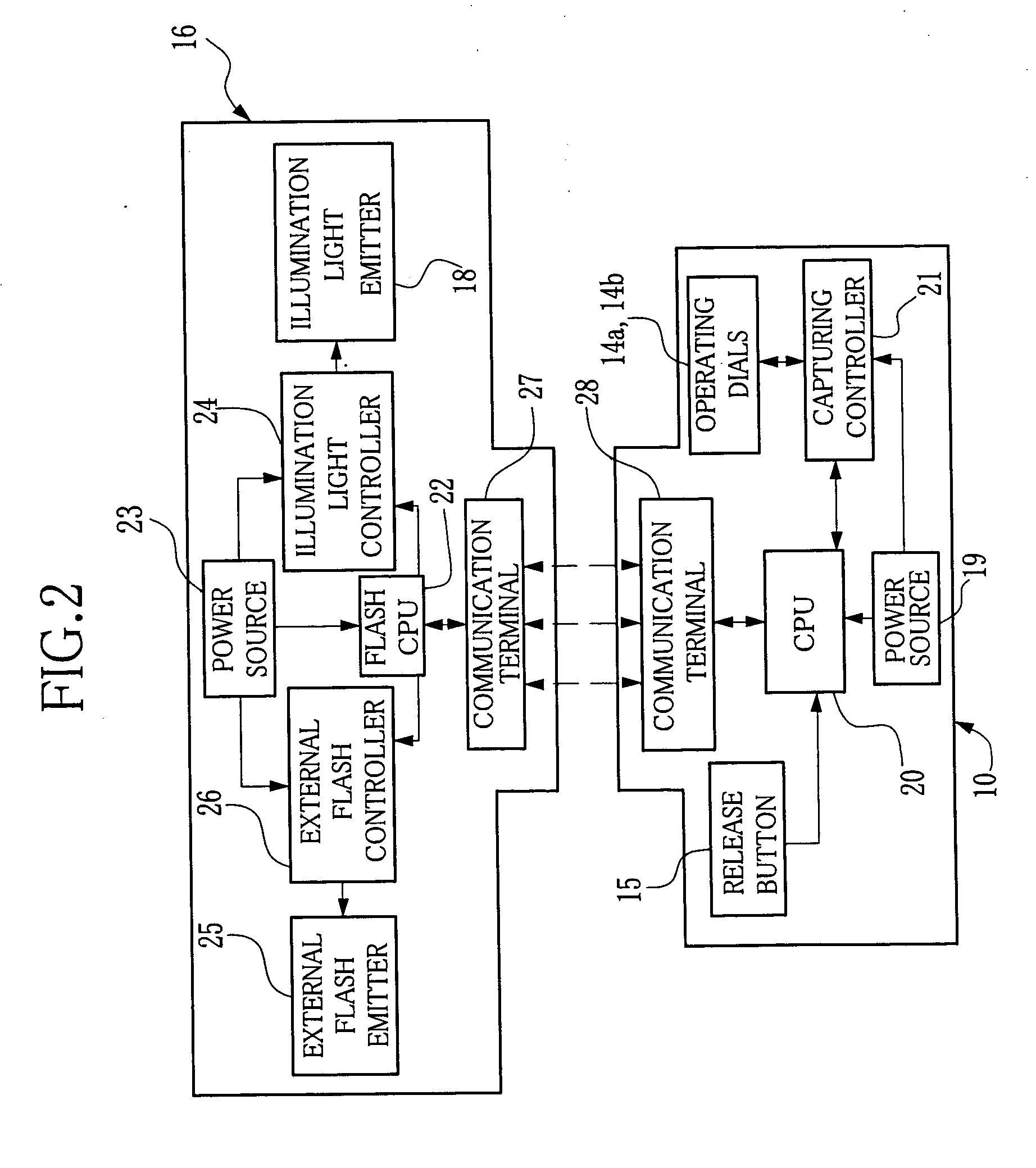
[0010] According to the present invention, the illumination light emitter provided on the external camera accessory illuminates the operating portion of the camera, thereby a user can easily and securely operate the operating portion. Moreover, the camera accessory is provided with the illumination operation member to turn on the illumination for the operating portion when needed, or the camera accessory is provided with the illumination detecting sensor to turn on the illumination for the operating portion only in dark places, so wasteful consumption of battery power can be reduced.
[0011] Furthermore, the communication section is provided between the camera and camera accessory to illuminate the operating portion in accordance with an operation of the camera, so the operating portion can be illuminated automatically when the user requires illumination. This saves the user's labor.
[0013] Moreover, a power source of the illumination light emitter is set to ON state when the release button provided on the camera body is pressed halfway, and the power source can be shifted to OFF state when the release button is fully pressed, so the operation of illuminating can be simplified. Furthermore, the power'source of the illumination light emitter can be shifted to OFF state automatically after a certain period of time since the half-press of the button was stopped. This prevents wasteful consumption of the battery power due to ineffective illumination and saves a user's labor to turn off the power source of the illumination light emitter.

Problems solved by technology

However, when an image is captured in a dark environment such as outdoors at night or a dark room, a user needs to set a capturing condition by groping for the button, the dial and the ring or needs to prepare an extra light, which are operationally inconvenient.

Method used


Image

  • Camera accessory and camera
  • Camera accessory and camera
  • Camera accessory and camera

Examples


Embodiment Construction

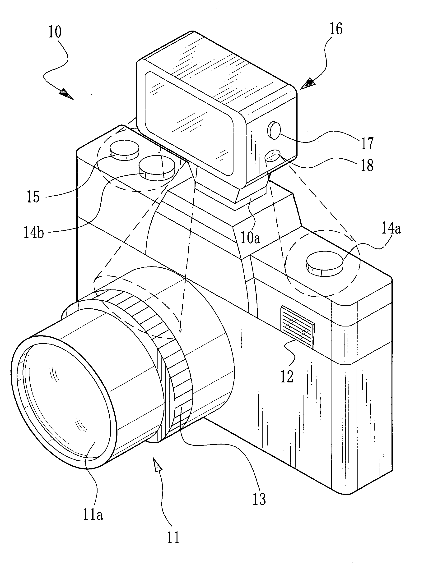
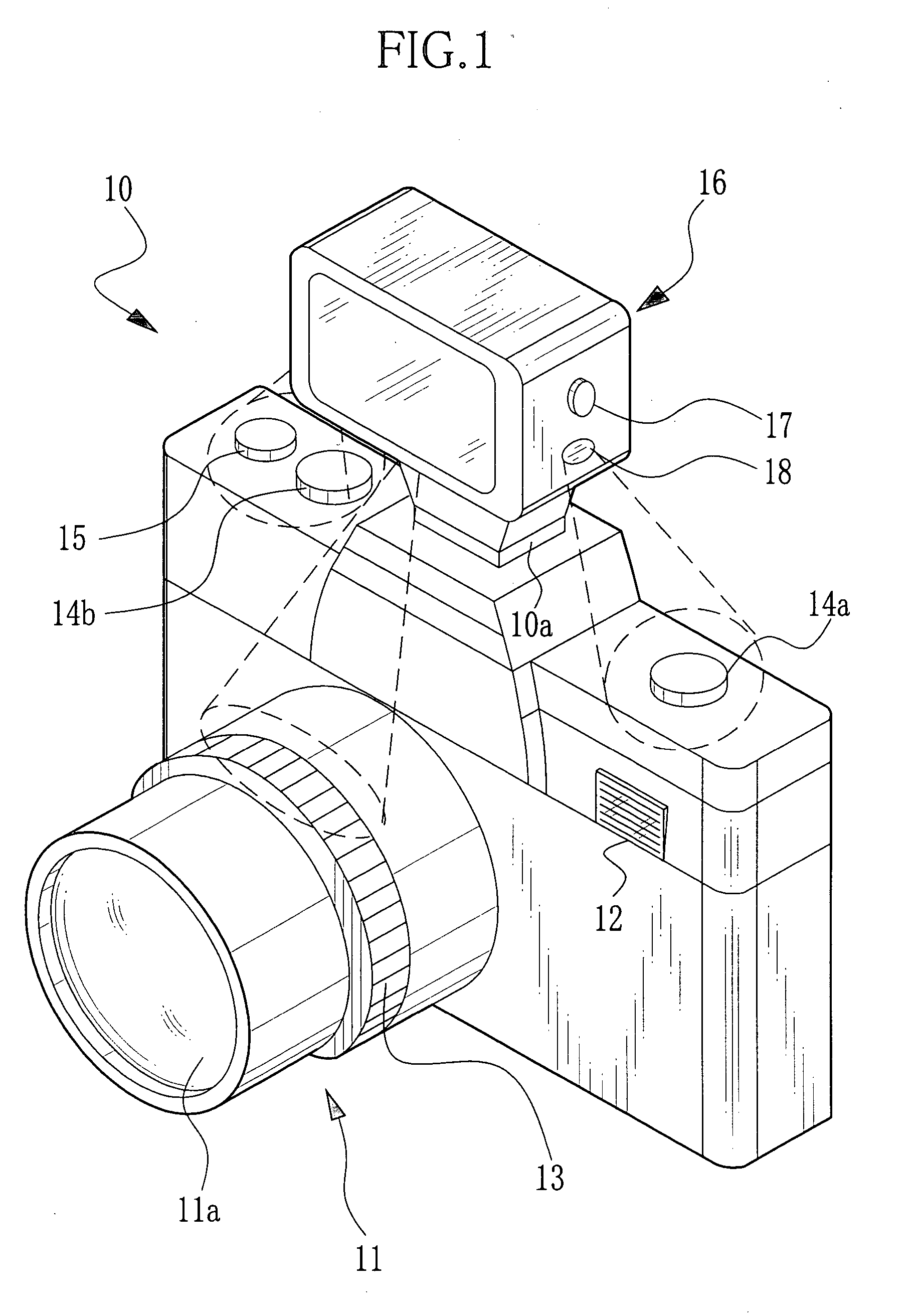
[0019] In FIG. 1, a front face of a digital camera (hereinafter referred to as a camera) 10 is provided with a lens barrel 11 having a taking lens 11a and an internal flash emitter 12 that emits flashlight to a subject. The lens barrel 11 includes an operation ring 13. The operation ring 13 is, for example, a focus ring that rotates to adjust focus of the taking lens 11a. The operation ring 13 may also be an aperture ring or a zoom ring. Further, the operation ring 13 may adjust focusing and zooming by rotation thereof and adjust aperture by slide thereof. A back face of the camera is provided with an LCD (liquid crystal display) to display a through image, a recorded image, and a screen for setting capturing condition. An upper face of the camera 10 is provided with operating dials 14a and 14b and a release button 15. When a subject is distant from the camera, an external flash device 16 is used as an accessory and attached to an accessory shoe 10a. A press of the release button 15...


PUM


Abstract

A side face of an external flash device is provided with an illumination operation button, and side and lower faces thereof are provided with illumination light emitters. Each of the illumination light emitters has a built-in LED and turns on by pressing the illumination operation button. When an image is captured under a dark environment, a user can operate the operation ring, and operating dials and under the illumination.

Description

FIELD OF THE INVENTION [0001] The present invention relates to a camera accessory and a camera provided with an illuminator to illuminate an operating portion of the camera that is operated by a user. BACKGROUND OF THE INVENTION [0002] A camera is provided with operations such as a dial or buttons for setting a capturing mode, a sensitive dial for setting ISO sensitivity, a focus ring for adjusting a focal distance, and an aperture ring for adjusting an aperture. A user operates these operation members prior to image capturing. In order to take a beautiful photo, a camera having various functions is sold in the market. The camera is generally provided with a button for selecting functions. From the reason above, the number of the buttons, dials and rings operated by the user increases. [0003] Most cameras have a built-in flash device (hereinafter referred to as an internal flash device). The internal flash device emits small amount of light, so when a subject that is distant from th...

Claims


Application Information

Patent Timeline
IPC IPC(8): G03B17/18
CPCG03B17/18
Inventor SENBA, TAKEHIKO
Owner FUJIFILM CORP
Learn More