
Liquid container and liquid filling method

a liquid container and liquid technology, applied in the direction of level indicators, instruments, printing, etc., can solve the problems of difficult printing quality or maintenance of recording equipment, degraded detection precision, and likely damage to the liquid ejector head, so as to improve the liquid detection precision. , the effect of excellent liquid detection precision

Inactive Publication Date: 2007-05-17
SEIKO EPSON CORP
View PDF4 Cites 19 Cited by
  • Summary
  • Abstract
  • Description
  • Claims
  • Application Information

AI Technical Summary

Benefits of technology

The invention provides a liquid container with a function of detecting when the liquid level reaches a predetermined level and a good liquid filling method that prevents bubbles from remaining in the container. The liquid container includes a liquid detection unit that uses a piezoelectric detection unit to detect changes in liquid level or pressure. The container has a liquid detection chamber that is pressurized and discharges liquid through a liquid discharge port. The liquid detection unit includes a movable member that moves to partition the detection space, a recess portion that forms a vibration reaction region, and a piezoelectric detection unit that applies vibration to the recess portion and detects a free vibration state. The container also has a liquid detection chamber that is sealed with a deformable film and can be easily deformed according to the liquid level or pressure. The invention provides a reliable and accurate liquid detection method that prevents bubbles from remaining in the container and improves the precision of liquid detection.

Problems solved by technology

A liquid ejecting head of a liquid ejecting apparatus, such as a printing apparatus, a microdispenser, or a commercial recording apparatus that requires ultrahigh printing quality, receives a liquid from a liquid container, However, if the liquid ejecting head operates in a state where the liquid is not supplied, idle printing occurs, and thus the liquid ejecting head is likely to be damaged.
However, in the liquid detection unit described in Patent Document 1, the liquid residual quantity can be detected with comparatively high precision, but the residual quantity of ink contained in the flexible pouch is affected by bending or wrinkles of the pouch since the rigid body moves according to the deformation of the flexible pouch, and thus detection precision may be degraded.
As a result, there may be a difficulty in printing quality or maintenance on the recording apparatus.

Method used


Image

  • Liquid container and liquid filling method
  • Liquid container and liquid filling method
  • Liquid container and liquid filling method

Examples


first embodiment

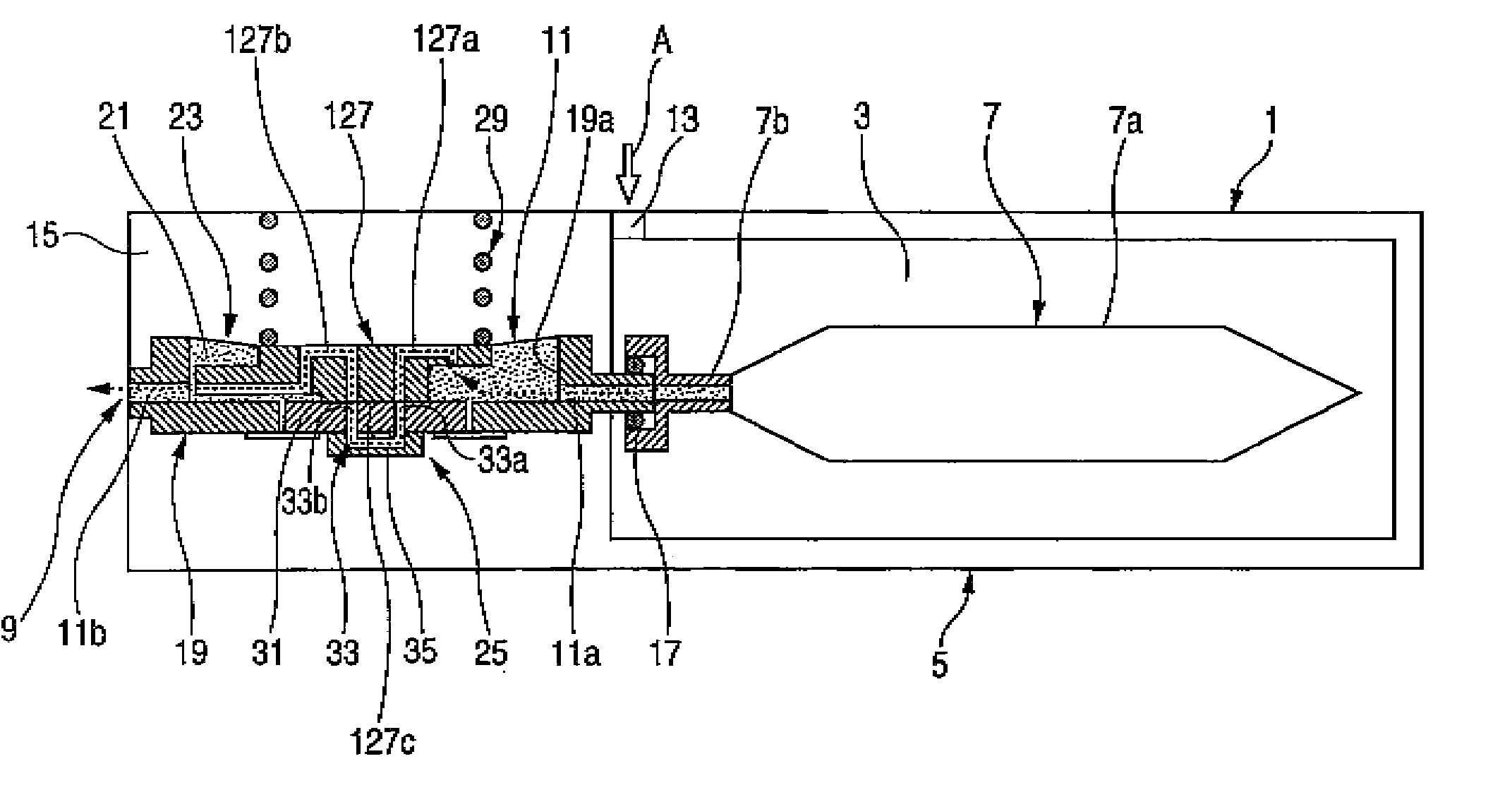
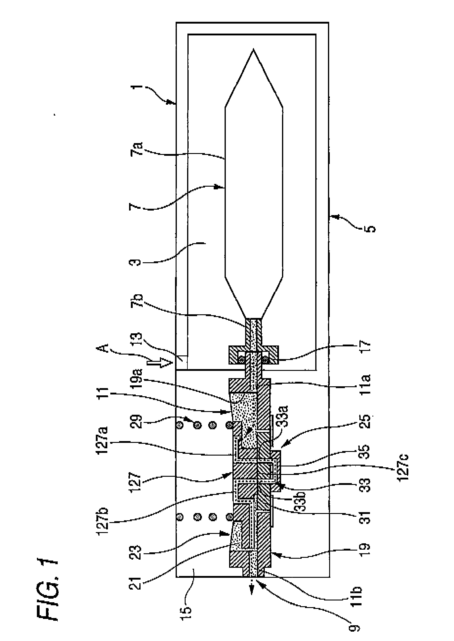
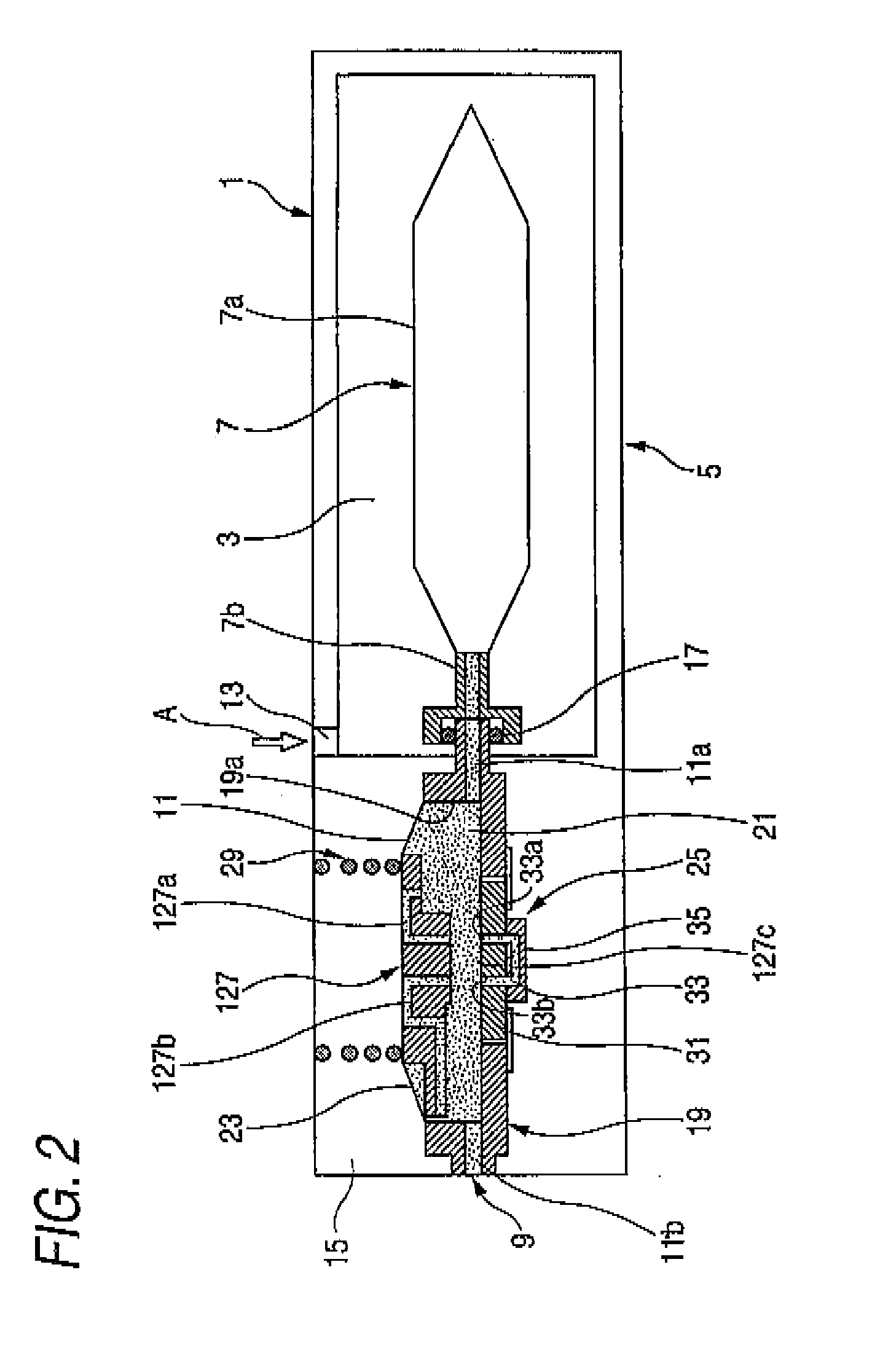
[0128]FIG. 1 is a longitudinal cross-sectional view of a liquid container according to the invention. FIG. 1 shows a state where a liquid is absorbed from a liquid containing portion in a non-pressurized state to a liquid supply port. FIG. 2 is a longitudinal cross-sectional view showing a state where the liquid containing portion of the liquid container shown in FIG. 1 is pressurized.

[0129] The liquid container 1 of the first embodiment is an ink cartridge that is detachably mounted on a cartridge mounting portion of an ink jet recording apparatus (liquid consuming apparatus) (not shown) and supplies ink (liquid) to a printing head provided in the recording apparatus.

[0130] As shown in FIG. 1, the liquid container 1 includes a container main body 5, in which a pressure chamber 3 is partitioned to be pressurized by a pressure unit (not shown), an ink pack (liquid containing portion) 7 that stores ink, is accommodated in the pressure chamber 3, and discharges ink stored therein from...

second embodiment

[0166]FIG. 3 is a longitudinal cross-sectional view of a liquid container according to the invention.

[0167] A liquid container 101 of the second embodiment uses a pressure receiving plate 227 that is replaced for the pressure receiving plate 127 in the liquid container 1 of the first embodiment. Other parts than the pressure receiving plate 227 are the same as those of the liquid container 1. The same parts are represented by the same reference numerals, and the descriptions thereof will be omitted.

[0168] As shown in FIG. 3, in the pressure receiving plate 227 of the liquid container 101 according to the second embodiment, a first flow passage 227a and a second flow passage 227b that are two flow passages connecting the detection space partitioned through the cooperation of the ink guide path 33 to the sensor chamber 21 are provided.

[0169] The first flow passage 227a as one of the two flow passages extends to the vicinity of the ink inlet port 11a.

[0170] In the liquid container 10...

third embodiment

[0172]FIG. 4 is a longitudinal cross-sectional view of a liquid container according to the invention.

[0173] A liquid container 102 of the third embodiment uses a pressure receiving plate 327 that is replaced for the pressure receiving plate 127 in the liquid container 1 of the first embodiment. Other parts than the pressure receiving plate 327 are the same as those of the liquid container 1. The same parts are represented by the same reference numerals, and the descriptions thereof will be omitted.

[0174] As shown in FIG. 4, in the pressure receiving plate 327 of the liquid container 102 according to the second embodiment, a first flow passage 327a and a second flow passage 327b that are two flow passages connecting the detection space partitioned through the cooperation of the ink guide path 33 to the sensor chamber 21 are provided.

[0175] The first flow passage 327a and the second flow passage 327b as the two flow passages extend to the vicinities of the ink inlet port 11a and the...


PUM


Abstract

A liquid container includes: a liquid containing portion that is pressurized by a pressure unit and discharges a liquid stored therein through a liquid discharge port; a liquid supply port that supplies the liquid to an external liquid consuming apparatus; and a liquid detection unit that is interposed between the liquid containing portion and the liquid supply port, wherein the liquid detection unit includes: a liquid detection chamber that has a liquid inlet port to be connected to the liquid discharge port of the liquid containing portion and a liquid outlet port to be connected to the liquid supply port; a movable member that is movably accommodated in response to a liquid containing amount of the liquid detection chamber; a recess portion that partitions a detection space in cooperation with one surface of the movable member when the liquid containing amount of the liquid detection chamber becomes a predetermined amount or lesser and a piezoelectric detection unit that applies vibration to the recess portion and detects a free vibration state according to the applied vibration, and wherein the movable member is provided with two flow passages that connect the detection space partitioned through the cooperation of the recess portion to the liquid detection chamber.

Description

TECHNICAL FIELD [0001] The present invention relates to a liquid container and a liquid filling method, and in particular, to a liquid container that supplies a predetermined liquid to a liquid consuming apparatus, such as a liquid ejecting head ejecting minute droplets or the like, and a liquid filling method that fills a liquid in a liquid detection unit of the liquid container. BACKGROUND ART [0002] A liquid ejecting head of a liquid ejecting apparatus, such as a printing apparatus, a microdispenser, or a commercial recording apparatus that requires ultrahigh printing quality, receives a liquid from a liquid container, However, if the liquid ejecting head operates in a state where the liquid is not supplied, idle printing occurs, and thus the liquid ejecting head is likely to be damaged. In order to prevent this problem, it is necessary to monitor a liquid residual quantity in the container. [0003] Examples of the recording apparatus include various apparatus that have a liquid d...

Claims


Application Information

Patent Timeline
Patent Type & Authority Applications(United States)
IPC IPC(8): B41J2/175
CPCB41J2/17566B41J2002/17516B41J2002/17583G01F23/296G01F23/2965B41J2/17513B41J2/17523G01F23/2966B41J2/175B41J2/17506B41J2/17509B41J2/17503
Inventor KIMURA, HITOTOSHI
Owner SEIKO EPSON CORP
Learn More