Knife sharpener

a sharpener and blade technology, applied in the field of knife sharpeners, can solve the problems of affecting the precise angle at which the knife meets the sharpening rod, the use of a fixed stop member on the front of the housing plate, and the use of a housing plate with all components attached to the front of their uni

Inactive Publication Date: 2007-05-10
SOUTHERN MECHANICAL & STRUCTRUAL
View PDF11 Cites 8 Cited by
  • Summary
  • Abstract
  • Description
  • Claims
  • Application Information

AI Technical Summary

Benefits of technology

[0009] It is an object of the present invention to provide an improved knife sharpener.
[0010] It is another object of the present invention to provide a knife sharpener that is more durable, and easier to use.
[0012] It is yet a further object of the present invention to provide a knife sharpener that utilizes a pair of curved sharpening rods that are controlled to provide optimal angles and pressures and which obtain even and consistent edge realignment and / or edge retrieval, regardless of the sharpening technique being employed by the particular person who sharpens the knife.
[0013] The foregoing and other objects of the invention are realized with a knife sharpening unit that supports on a housing plate a pair of sharpening rods that are curved to specific dimensions for maximizing the knife sharpener's ability to utilize and engage an impact-absorbing flexible bumper arm assembly. The flexible bumper arm assembly controls and guides the sharpening rods at their end-of-travel point, in a manner that alters the angle of intersection between the sharpening rods and the pressures applied to the blade of the knife to obtain even and consistent edge realignment.

Problems solved by technology

One drawback of the prior art is that at the point that the rods reach an end-of-motion stopper, continued pressing of the knife against the V-shaped intersection results in some loss of control over the precise angles at which the knife meets that sharpening rods.
Another drawback of prior art 5,478,272 and 5,655,959 patent is the use a fixed stop member on the front of the housing plate.
Another drawback of all prior art is the use of a housing plate having all components attached to the front of their unit.
Prior art do not have the protective positioning of the hardware being placed on the reverse side of the housing unit, away from the operator.
There is no leverage, protection, or strength when all the hardware and adjustments are facing the operator.
The rods bend toward the operator, adding more stress and fatigue.
Another drawback of all prior art is that no recessed slot is used to guide the knife.

Method used


Image

  • Knife sharpener
  • Knife sharpener
  • Knife sharpener

Examples


Embodiment Construction

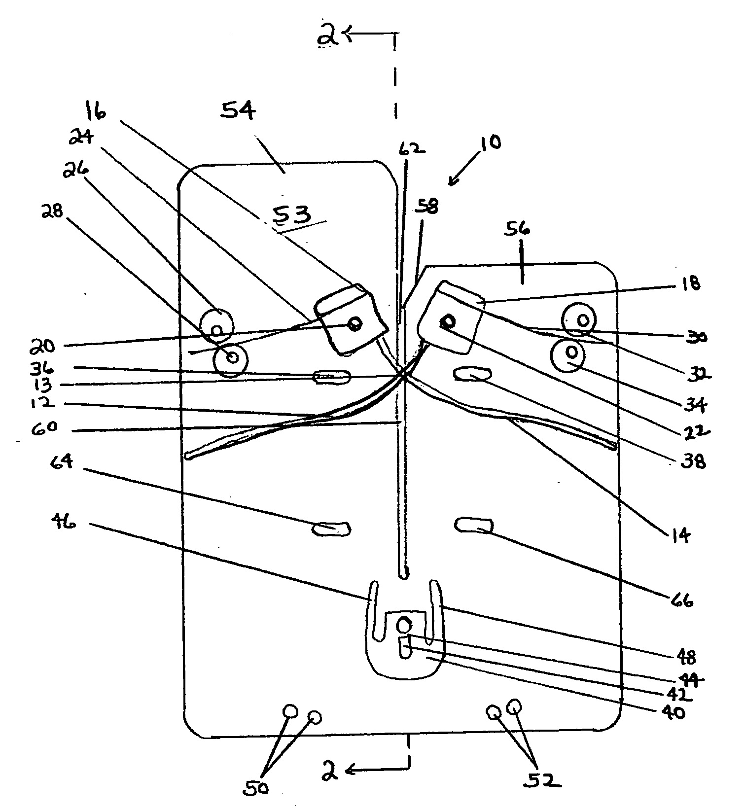
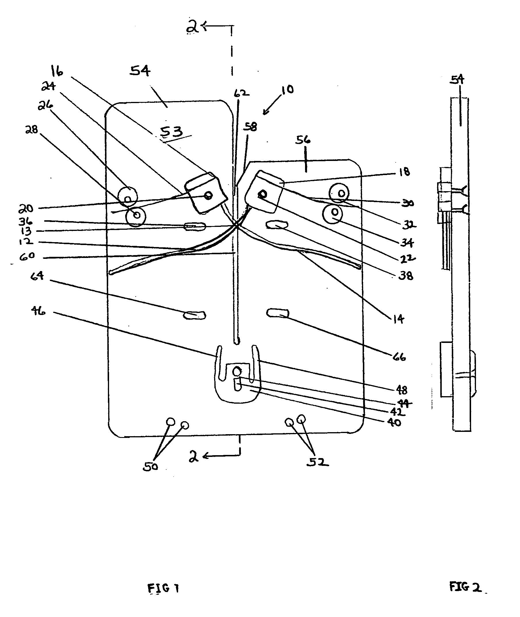
[0023] With reference to the drawings and primarily FIG. 1, the knife sharpener 10 of the present invention is comprised in the main of a housing plate 53 with two main sections 54 and 56 that are separated by a knife slot 60. The housing plate supports a pair of pivotally movable sharpening rods 12, 14 that are resiliently biased toward an initial position by spring arms 24, 30, the sharpening rods crossing one another at a movable V-shaped intersection point 13, the location of which moves along the slot 60, as a knife is pressed down the slot 60.

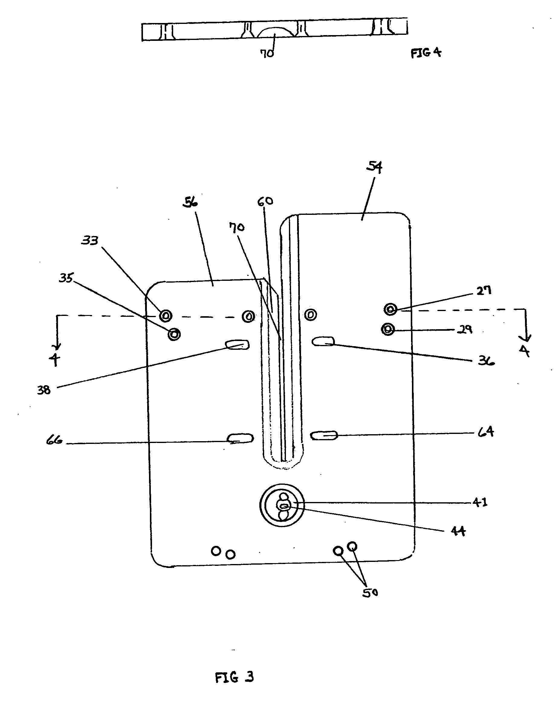
[0024] The housing plate 53 is preferably made of a solid, ½ inch thick UHMW and / or high-density polyethylene, durable, one-piece construction material. It has been designed so that the knife blade 77 (FIG. 8) will avoid cutting into the housing plate 53 during normal use. The blind high wall 55 (FIG. 8) on the right side of the housing plate 53 helps guide the blade 77 down into the sharpening slot 60.

[0025] Four adjustable upper and l...


PUM


Abstract

A knife sharpener comprising a housing plate supporting a pair of special treated sharpening rods that are curved to a specified dimension for maximizing the knife sharpener's ability to utilize and engage adjustable flexible bumper arms mounted on a positive stop that provides the sharpener's rods best angles and pressure for obtaining an even, consistent edge realignment, no matter what sharpening technique is used. Adjustable spring and cam mechanisms enable easy positioning of the initial, crossing-point of the sharpening rods over the center of a sharpening slot. A stop member and resilient device are used as a single integral stop unit vertically moveable and mounted on the rear face of the housing plate.

Description

BACKGROUND OF THE INVENTION [0001] The present invention relates to knife sharpeners, and more particularly, to a knife sharpener that utilizes a pair of curved sharpening rods that engage and interact with an impact-absorbing flexible bumper arm assembly which controls and guides the sharpening rods to optimal angles and pressures that enhance obtaining even and consistent edge alignment of a knife regardless of what sharpening techniques are used. [0002] Various blade or knife sharpening devices are known in the prior art that utilize a pair of sharpening rods that are pivotally mounted and cross one another over a slot which receives and guides the blade to be sharpened. Representative of this prior art are U.S. Pat. Nos. Cozzini 5,478,272, Bloomington 5,040,435 and Juranitch 5,655,959, Inman 4,550,632, Gangelhoff 5,440,953, Juranitch 4,934,110 the contents of which are incorporated by reference herein. [0003] As described in the 5,478,272 and 5,655,959 patents, the sharpening ro...

Claims


Application Information

Patent Timeline
IPC IPC(8): B21K11/00B21K5/12
CPCB24D15/081
Inventor HARDEN, KATHLEEN
Owner SOUTHERN MECHANICAL & STRUCTRUAL
Why Eureka
Try Eureka