Eureka AIR delivers breakthrough ideas for toughest innovation challenges, trusted by R&D personnel around the world.

Monolithic dual-purpose trailer

a dual-purpose, monolithic technology, applied in the direction of transportation, transportation items, loading/unloading vehicle arrangment, etc., can solve the problems of non-loading condition, wasteful and considered undesirable, relatively complicated conversion,

Active Publication Date: 2007-05-03
HICKS RANDALL
View PDF29 Cites 70 Cited by
  • Summary
  • Abstract
  • Description
  • Claims
  • Application Information

AI Technical Summary

Benefits of technology

[0011] Additional objects, features and advantages of the present invention will become more readily apparent from the following detailed description o

Problems solved by technology

Since such trailers are designed to transport only one type of load, often the trailers made a trip one-way loaded and make a return trip empty.
Traveling in a non-loaded condition is wasteful and considered undesirable because of the large cost of fuel and labor costs associated with moving an empty trailer.
The patent then teaches a relatively complicated conversion system which supposedly allows an operator to convert the trailer from a hopper configuration to a box configuration.
Apparently the difficulties involved with these types of convertible trailers in terms of the effort required to convert them from one configuration to another has been so great that none of them are currently in mass production except for a trailer produced by Western Trailers.
Even the Western Trailer unit has so many problems with the conversion process that divers will only convert them seasonally.
The trailers still often travel in a non-load condition because of the labor and safety issues involved with converting the trailer is so great it is cheaper to run the trailer empty.
Also in all of the above-mentioned convertible trailers and indeed for flat bed trailers generally there is the additional problem of the trailers having weakness in the longitudinal direction that allows undesirable longitudinal flexing.

Method used


Image

  • Monolithic dual-purpose trailer
  • Monolithic dual-purpose trailer
  • Monolithic dual-purpose trailer

Examples


Embodiment Construction

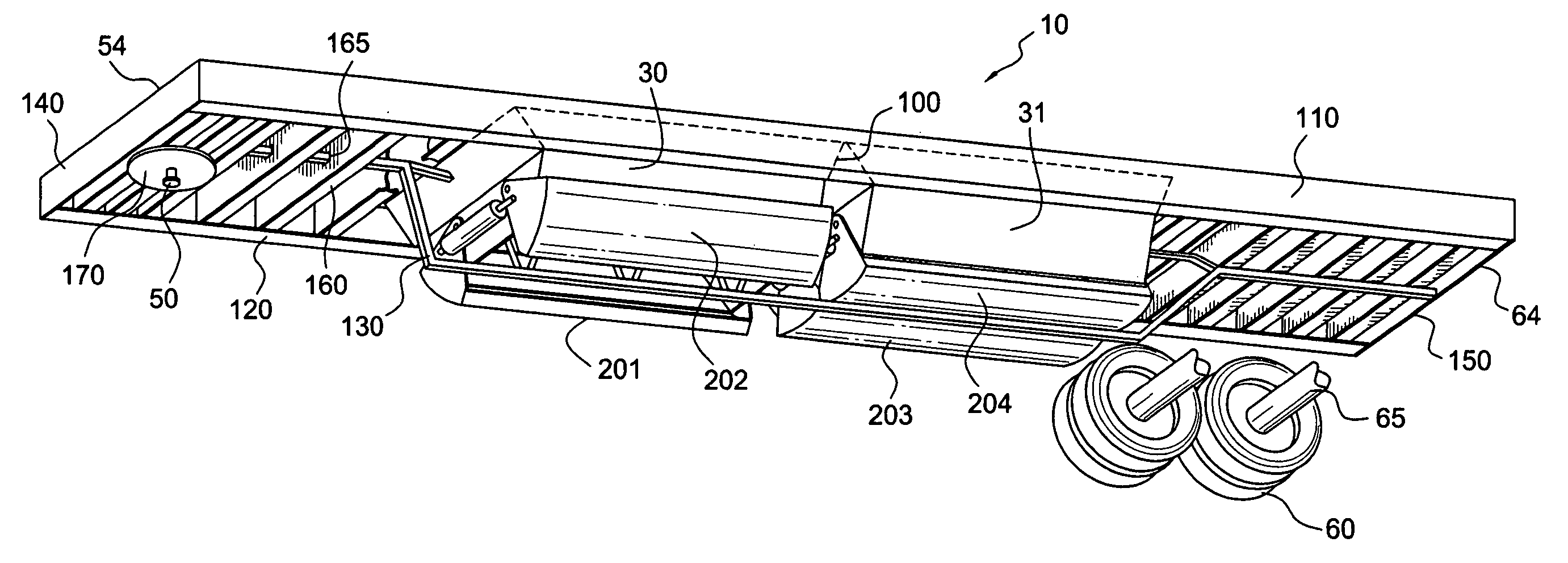
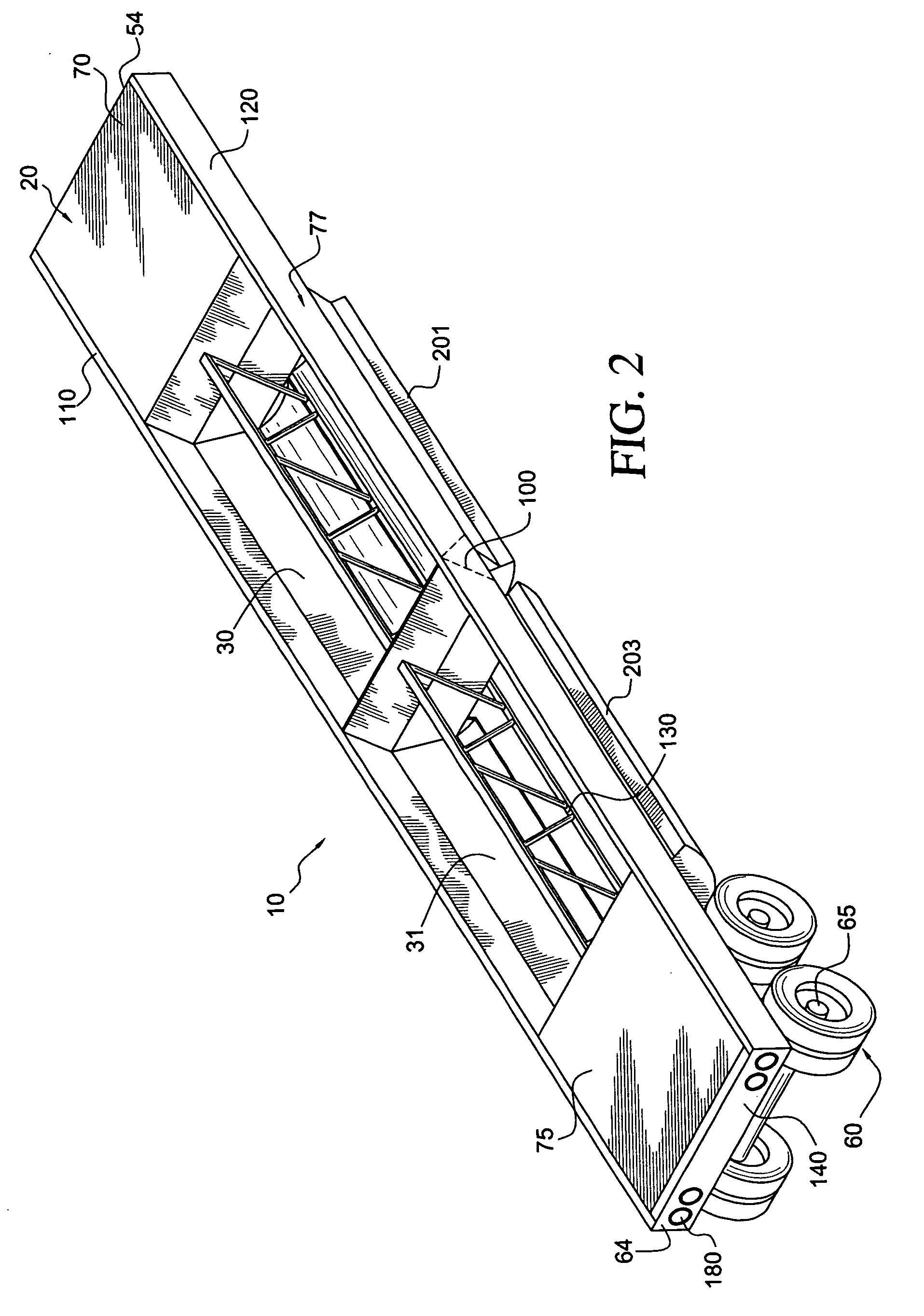
[0019] With initial reference to FIGS. 1-3, there is illustrated a nonconvertible monolithic dual-purpose trailer 10 constructed in accordance with a preferred embodiment of the invention. Trailer 10 has a longitudinally extending deck 20 that is preferably flat. First and second hoppers 30, 31 are located below deck 20. Deck 20 is capable of transporting any load typically loaded on a flatbed trailer. For example, discrete cargo such paper rolls, coils of steel, lumber and the like are transported on deck 20. The first and second hoppers 30, 31 are capable of carrying commutated, loose bulk material such as sand or crushed stone.

[0020] Generally trailer 10 is supported by a king pin 50 at a first end 54 and by wheels 60 at a second end 64. Wheels 60 are mounted on axels 65 that in turn are mounted to trailer 10 by a suspension system (not shown) as is well known in the art. As shown there are eight wheels however it is envisioned that the number and placement of the wheels could c...


PUM


Abstract

A monolithic dual-purpose trailer for transporting cargo includes a frame including two longitudinally extending side rails and a central reinforcing member in the form of an engineered truss is located between the two side rails. Wheels are mounted to the frame. A deck including a load bearing surface with a grate is formed on the frame. Hoppers are positioned below the grate. The frame is formed as one solid welded unit. The deck has a portion formed of flat aluminum. A perimeter frame rail is located around the deck. The trailer can transport multiple types of loads and does not have to be converted from one mode to another and additionally has reduced longitudinal flexing.

Description

BACKGROUND OF THE INVENTION [0001] 1. Field of the Invention [0002] The present invention pertains to the art of hauling cargo from place to place and more particularly to trailers used to haul either discrete cargo that is typically transported on a flat bed and loose bulk cargo such as crushed stone or sand that is typically transported in a hopper. [0003] 2. Discussion of the Prior Art In the past large discrete items of cargo have been traditionally transported on flatbed trailers and loose bulk cargo has been transported in trailers that have hoppers. Since such trailers are designed to transport only one type of load, often the trailers made a trip one-way loaded and make a return trip empty. Traveling in a non-loaded condition is wasteful and considered undesirable because of the large cost of fuel and labor costs associated with moving an empty trailer. [0004] In response to this problem Schmidt et al have proposed in U.S. Pat. No. 4,082,357 to start with a box-type semi-tra...

Claims


Application Information

Patent Timeline
IPC IPC(8): B60P1/56
CPCB60P1/56
Inventor HICKS, RANDALL
Owner HICKS RANDALL
Why Eureka
Eureka Blog
Learn More