
Single piece fuselage barrel

a single-piece, fuselage technology, applied in the direction of fuselages, transportation and packaging, other domestic objects, etc., can solve the problems of aircraft structure that is often subject to close scrutiny for its ability to resist bird strikes, excess weight, and more commonly, the effect of reducing the number of pieces

Active Publication Date: 2007-05-03
THE BOEING CO
View PDF49 Cites 87 Cited by
  • Summary
  • Abstract
  • Description
  • Claims
  • Application Information

AI Technical Summary

Benefits of technology

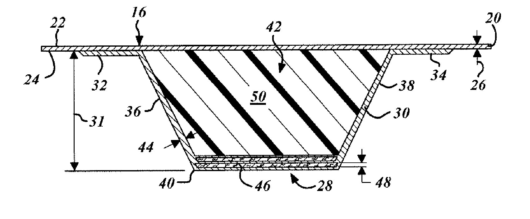
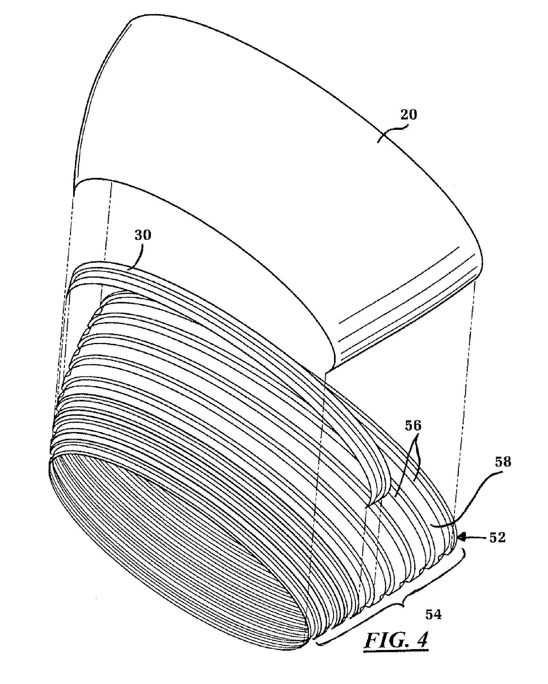
The present invention provides an aircraft stringerless fuselage structure that includes an impact compliant outer skin and a plurality of stiffeners integrated into the inner stringerless skin structure. The stiffeners are made of resin-impregnated stiffener fibers that are not aligned with the resin-impregnated skin fibers. The technical effect of this invention is to provide a more efficient and lightweight aircraft fuselage structure that reduces the need for stringers and increases impact resistance.

Problems solved by technology

Aircraft structures often provide complex and costly challenges to both design and manufacturing.
Additionally, this portion of the aircraft comes under close scrutiny for its ability to have bird strike resistance.
As such, section 41 barrel sections are often over designed which may lead to excess weight and more commonly excess cost.
Often the outer skin and other structural supports are formed from aluminum which when overloaded may result in costly damage or repair.
Bird strike incidents, even on designs that are not overloaded, may leave large dents in the aluminum structure that eventually require costly repairs.
When overloaded, however, portions of the aluminum structure may rupture requiring extremely expensive repair or replacement.
The aluminum skin also requires complex manufacturing and assembly as the skin is commonly backed by very heavy and complex beam structures.
Structures such as stringers are required for support and add both considerable cost in addition to weight to the aircraft.
The complex curvatures of the skins, especially in the nose region, often require manufacturing using expensive computer controlled machines.
The quantity and complexity of manufacturing and assembling these aluminum structures often make section 41 the most expensive barrel section in the entire aircraft body.

Method used


Image

  • Single piece fuselage barrel
  • Single piece fuselage barrel
  • Single piece fuselage barrel

Examples


Embodiment Construction

[0012] Referring now to FIG. 1, which is an illustration of an aircraft stringerless fuselage section 10 in accordance with the present invention. The section 10 is illustrated as the commonly known section forty-one section although it is contemplated that the present invention is applicable to a variety of aircraft build zones. The section 10 presented includes the nose portion 12 in addition to the cockpit windows 14 wherein the geometry of the barrel section 10 is varied considerably in addition to requiring additional strength requirements. One of these requirements is the ability to withstand bird impact loads during operation. Existing designs contemplate the use of aluminum skins and complex and costly support structures underneath such as the use of complex curved stringers or other beams. In addition, existing approaches often result in costly repairs during bird strike due to their rigid approach to bird strike protection.

[0013] The present invention accomplishes both we...


PUM

PropertyMeasurementUnit
thicknessaaaaaaaaaa
thicknessaaaaaaaaaa
thicknessaaaaaaaaaa

Abstract

In accordance with the present invention an aircraft stringerless fuselage structure is provided comprising an impact compliant outer skin having a plurality of resin impregnated skin fibers forming an outer skin surface, an inner stringerless skin surface, and a skin thickness. A plurality of stiffeners is included, each comprising a plurality of resin impregnated stiffener fibers integrated into the inner stringerless skin structure. The plurality of resin impregnated skin fibers are not aligned with the plurality of resin impregnated stiffener fibers.

Description

TECHNICAL FIELD [0001] The present invention relates generally to an apparatus and method for reducing the cost and complexity of the fuselage barrel section of an aircraft and more particularly to an apparatus and method for integrating a cost effective and compliant structure that absorbs energy during bird strike impact. BACKGROUND OF THE INVENTION [0002] Aircraft structures often provide complex and costly challenges to both design and manufacturing. The underlying structures must not only meet strength requirements, but must also survive constant weight reduction requirements and manufacturing cost and time restraints. As such, a reanalysis and creative investigation into existing structures bears the possible reward of considerable benefits during implementation. [0003] Such is the case with the fuselage section of the aircraft. Specifically the forward section commonly referred to as section 41. This fuselage section includes complex geometry and structure by way of the inclu...

Claims


Application Information

Patent Timeline
Patent Type & Authority Applications(United States)
IPC IPC(8): B64C1/00
CPCB29C70/44B29K2105/246B29K2995/0089Y02T50/433B64C1/068B64C1/12B64C2001/0072B29L2031/3082B64F5/10Y02T50/40B64C1/0683B29C70/30B64C1/06B29C70/202B29K2105/108B29K2105/253B29K2307/04B29K2309/08
Inventor KISMARTON, MAX U.ANDREWS, FRANCIS E.KOCH, WILLIAM J.
Owner THE BOEING CO
Learn More