
Dust pan broom stand

a technology for dust pans and dust pans, which is applied in the direction of brushes, carpet cleaners, floor cleaners, etc., can solve the problems of increasing weight, prone to damage to bristles and cleaning/maintenance heads and surfaces during storage, and deformation of bristles,

Inactive Publication Date: 2007-04-26
CROWLEYJONES LP
View PDF13 Cites 21 Cited by
  • Summary
  • Abstract
  • Description
  • Claims
  • Application Information

AI Technical Summary

Problems solved by technology

Conventional brooms and similar cleaning implements have bristles which can become deformed, ends split, bent, broken or otherwise damaged in storage.
Addition of features to the implements, for example, other tools fixed to the broom or storable thereon and the like, increase the weight, thereby further tending to damage bristles and cleaning / maintenance heads and surfaces during storage.

Method used


Image

  • Dust pan broom stand
  • Dust pan broom stand
  • Dust pan broom stand

Examples


Embodiment Construction

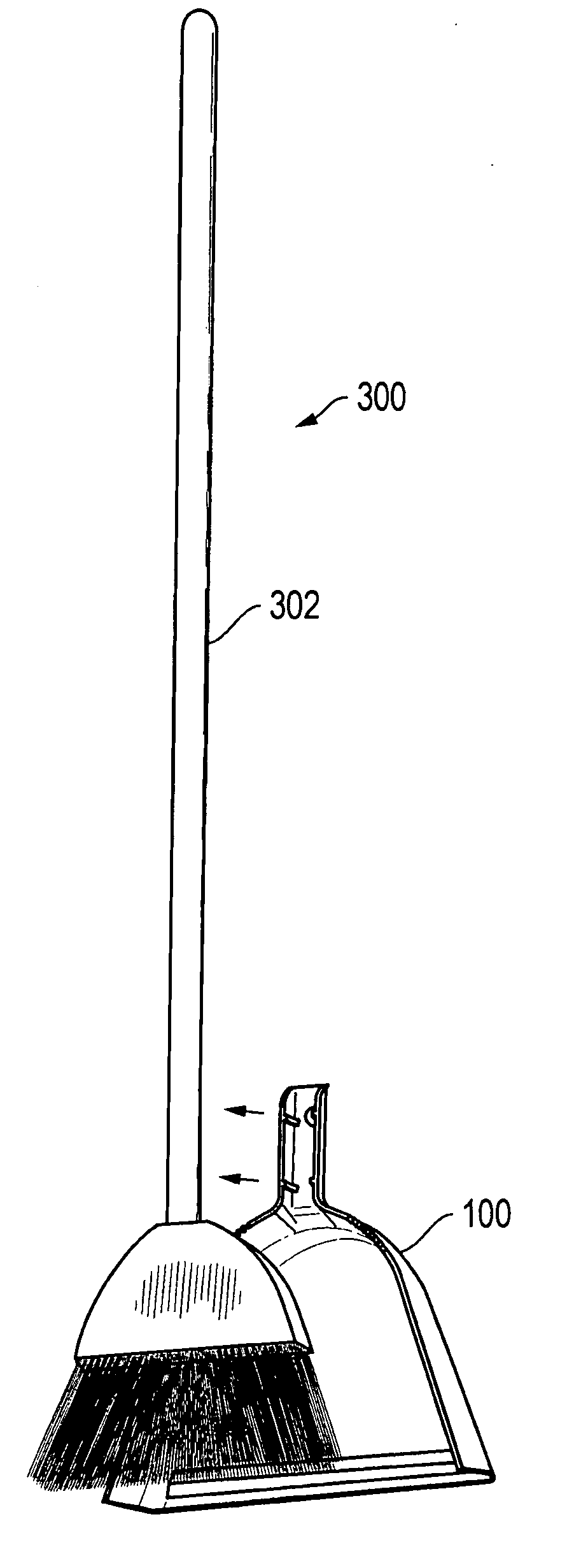
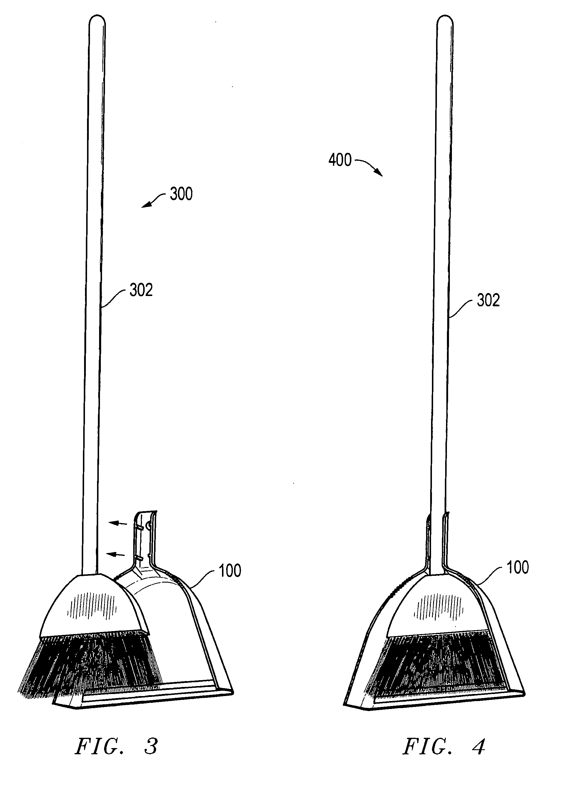
[0019] Referring to FIG. 1, a system 100 includes a scoop 102 connected to a handle 104. The scoop 102 has generally planar, generally wedge-shaped underside 106 connected at its periphery to a ridge 110 along all but a generally straight bottom edge 111. The ridge 110 has dual edges 110a,b that form angled corners A at the extents of the bottom edge 111. The bottom edge 111 and dual edges 110a,b planarly support the system 100 in an upright position on a generally flat surface, such as a floor. Moreover, as hereafter further described, the underside 106 is slightly larger than, but generally conforms to a shape of a broom head and bristles for use with the system 100 and the angled corners via the bottom edge 111 and dual edges 110a,b support the system 100 in such upright position, as mentioned, together with a broom having the head and bristles retained by the system 100.

[0020] The ridge 110 and underside 106 are connected at the underside 106 periphery, for example, via a joint...


PUM


Abstract

A dust pan includes a scoop having at least three planar contact points, such as edges of the scoop, on which the scoop can stand and a retainer connected to the scoop, to grip a handle of a broom. The dust pan is suitable to support the broom as so retained, and selectively maintains the dust pan with the broom for storage. In storing the combination of the dust pan and broom, the dust pan can sit in upright position on the planar contact points of the scoop. The dust pan supports the broom in upright position with the dust pan, and the broom bristles are shielded and do not bear the weight of the combination during such upright storage. Moreover, the combination can be capable of so supporting the broom without bristles touching an underlying surface.

Description

BACKGROUND OF THE INVENTION [0001] The present invention generally relates to cleaning devices and storage and device protective systems for such devices and, more particularly, relates to combined dust pan-stand assemblies removably integrable with brooms and the like, for storage and ready availability therewith and for protective maintenance thereof. [0002] Conventional brooms and similar cleaning implements have bristles which can become deformed, ends split, bent, broken or otherwise damaged in storage. For example, these implements are often stored leaning in a comer with the bristles on the ground supporting the weight of the implement. Addition of features to the implements, for example, other tools fixed to the broom or storable thereon and the like, increase the weight, thereby further tending to damage bristles and cleaning / maintenance heads and surfaces during storage. [0003] It would be a new and significant improvement in the art and technology to provide favorable cle...

Claims


Application Information

Patent Timeline
IPC IPC(8): A47L13/52
CPCA46B5/00A46B15/00A46B15/0097A46B2200/302A47L13/51A47L13/52
Inventor JONES, TERRY G.
Owner CROWLEYJONES LP
Learn More