
Sealing assembly with a diagonal seal

a sealing assembly and diagonal seal technology, applied in the direction of fluid pressure sealing joints, hose connections, mechanical appliances, etc., can solve the problems of large dead volume, large volume, complicated configuration, etc., and achieve the effect of preventing the occurrence of virtual leakage, simple assembly and reliable operation

Inactive Publication Date: 2007-04-19
G 2 ENG
View PDF6 Cites 0 Cited by
  • Summary
  • Abstract
  • Description
  • Claims
  • Application Information

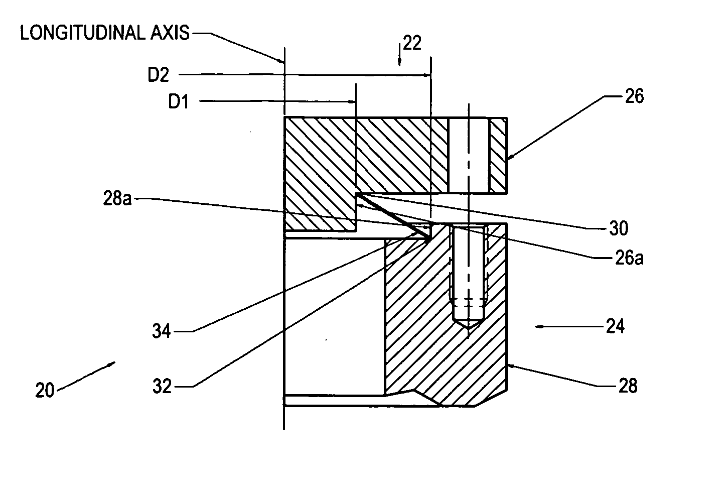
AI Technical Summary

Benefits of technology

[0009] It is an object of the present invention to provide a sealing system that is characterized by extreme simplicity of construction, converts the flange tightening force into a magnified sealing force, prevents occurrence of a virtual leak from a dead volume of the sealing unit, is simple to assembly, and reliable in operation.
[0010] A sealing system of the invention is characterized by extreme simplicity and low manufacturing cost.
[0011] In a most general form the sealing system of the invention may be described as a system having a longitudinal axis and a plane P perpendicular thereto and comprising a first clamping member, a second clamping member, and a sealing member between said first clamping members and said second clamping member. The aforementioned sealing member is defined by a generatrix following a closed-loop curved line around the longitudinal axis, and in any partial cross section in a plane perpendicular to a projection of a tangent of the closed-loop curved line onto the plane P, the first clamping member has a first thrust point at a first distance from the longitudinal axis, and the second clamping member has a second thrust point at a second distance from the longitudinal axis. These distances are different. The first thrust point and the second thrust point are located at different levels along the longitudinal axis. The generatrix of the sealing member has a substantially diagonal shape in the form of a line connecting the first thrust point and the second thrust point. This line forms a shallow angle to the plane P, and when the first clamping member and the second clamping member are moved towards each other along the longitudinal axis and clamped together by a clamping force, the clamping force is magnified and converted into a compression force in the sealing member along the aforementioned line, the magnification being equal to the reciprocal of the sine of the shallow angle, causing the shallow angle to become even shallower, thus increasing the magnification.
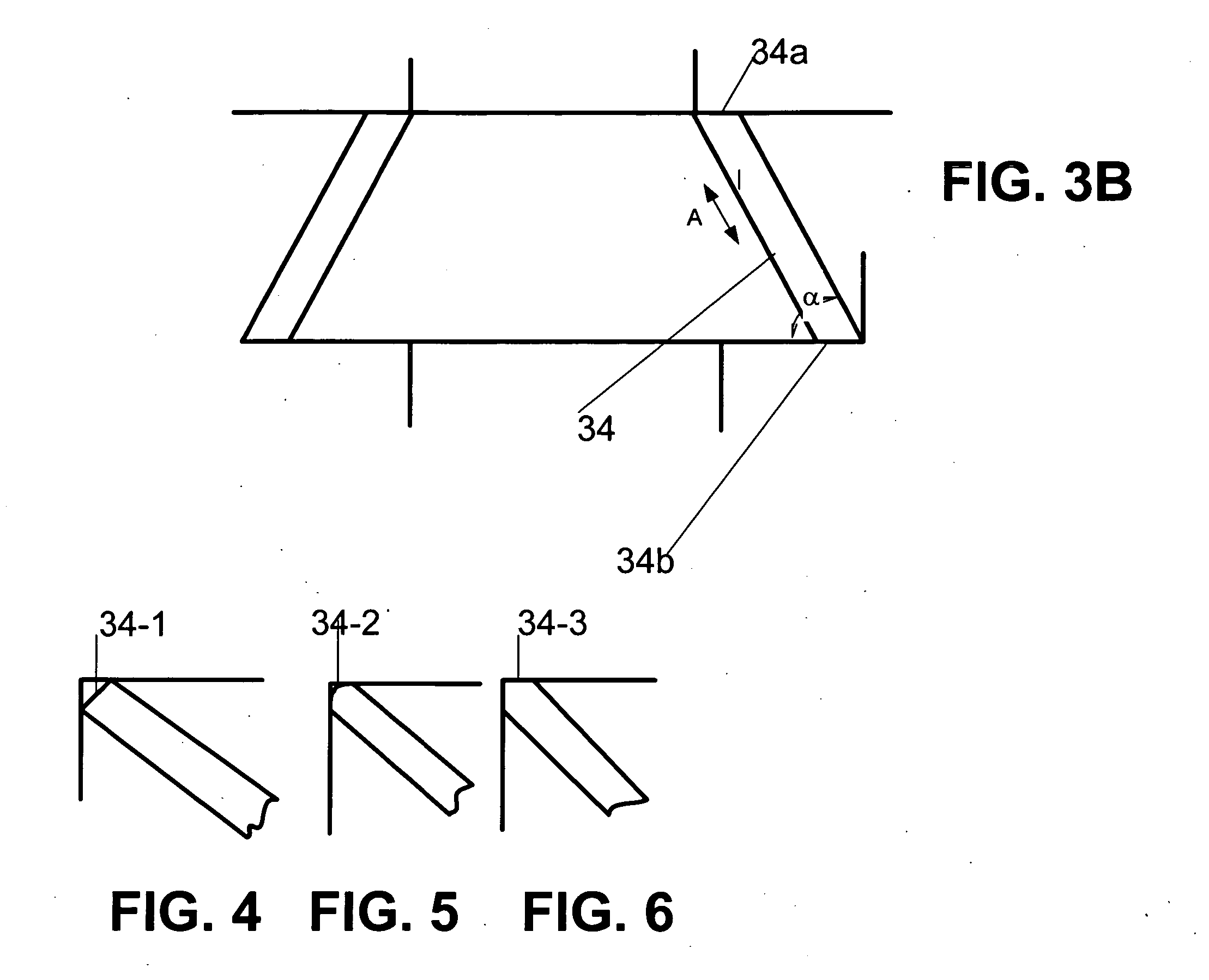
[0012] According to a simplified embodiment, the system consists of two symmetrical interconnectable clamping or flanged members having flanges with cylindrical shoulders. Each shoulder forms a corner with its respective flange. The outer diameter of the shoulder of one of the flanged members is smaller than the inner diameter of the shoulder on the mating flanged member. The sealing element of the system is comprised of a hollow body of revolution, preferably from a thin-wall metal in the form of a truncated cone. The sealing element is placed between the clamping or flanged members so that in a longitudinal cross-section of the assembly the sealing element forms a diagonal between the apices of the corners formed between the flanges and their respective shoulders. This diagonal is inclined at an acute angle to a plane perpendicular to the longitudinal axis of the sealing device. In other words, the truncated-cone sealing element is arranged so that the edge of its smaller-diameter end face thrusts against the circular line of intersection of the first flange with its smaller diameter shoulder, while the edge of its larger-diameter end face thrusts against the circular line of intersection of the second flange with its larger diameter shoulder. When in the assembling operation the flanges move towards each other and tightened by bolts, studs, or the like, and the distance between the flanges is shortened, the truncated-cone seal is compressed in the aforementioned diagonal direction, i.e., in the direction of the conical wall of the seal, and the compression force is magnified as the compression progresses.

Problems solved by technology

Although in this device a sealing force is to some extent amplified by the geometry of the seal and flanges, this amplification is very small.
The seal has a complicated configuration and in the case of ultra-high vacuum will produce a large dead volume that may create a virtual leakage.
A common disadvantage of all sealing systems known to the applicants, including those described above, is that they either have a complicated shape or complicated design composed of several components.
Therefore, the known sealing systems are expensive in manufacture and complicated in assembling and maintenance.
Furthermore, the structure of known sealing assemblies cannot provide conversion of flange tightening force into amplified sealing force but rather squeezes the seal without protection against leakage through the area of interface between the side walls of the seal and the mating surfaces of the flanges, or the like.

Method used


Image

  • Sealing assembly with a diagonal seal
  • Sealing assembly with a diagonal seal
  • Sealing assembly with a diagonal seal

Examples


Embodiment Construction

[0032] A sealing system according to one embodiment of the invention is shown in FIGS. 1 and 2, where FIG. 1 is a fragmental longitudinal sectional view of a sealing system illustrating positions of the parts prior to tightening the seal, and FIG. 2 is a view similar to FIG. 1 illustrating positions of the parts after the seal is tightened. FIGS. 1 and 2 show only the right half-part of the sealing system since the left half-part is symmetrical. In the embodiment of FIGS. 1 and 2, the sealing member has a regular shape and is made in the form of a truncated cone.

[0033] As can be seen from the drawings, the sealing system of FIGS. 1 and 2 that in general is designated by reference numeral 20 is characterized by extreme simplicity and low manufacturing cost. The system 20 consists of two interconnectable clamping or flanged members, hereinafter referred to as flanged members 22 and 24 having flanges 26 and 28 with cylindrical shoulders 26a and 28a. Each shoulder forms a corner with i...


PUM


Abstract

In a most general form the sealing system of the invention may be described as a system comprised of a pair of clamping members and a sealing member between them. The sealing member is defined by a generatrix following a closed-loop curved line around the longitudinal axis. In any partial cross section in a plane perpendicular to a projection of a tangent of the closed-loop curved line onto the plane P, the generatrix of the sealing member has a substantially diagonal orientation between the clamping members. When the clamping members are moved towards each for clamping the sealing member, the axial clamping force is magnified and converted into a compression force along the generatrix.

Description

FIELD OF THE INVENTION [0001] The present invention relates to the field of sealing devices, and more particularly, to metallic sealing of the joints between opposed parallel surfaces such as for instance, the end flanges by which a pressurized content of a vessel, cylinder, etc. is separated and sealed from the surrounding atmosphere or from another pressurized medium. In such assemblies the flanges are normally connected together by studs, or bolts with nuts, or wedged together by other rings. The sealing assembly of the invention may find application in high-pressure or high-vacuum systems where leakage of the medium may be critical. BACKGROUND OF THE INVENTION [0002] There exists a great variety of sealing assemblies and systems for sealing containers or vessels that are filled with a gaseous or liquid media under high-pressure or high-vacuum and that are closed and sealed via interconnection of two flanged elements fixed to each other by bolts or studs with nuts. [0003] For exa...

Claims


Application Information

Patent Timeline
Patent Type & Authority Applications(United States)
IPC IPC(8): F16L17/00
CPCF16L17/00
Inventor SHELEF, GAD
Owner G 2 ENG
Learn More