Eureka AIR delivers breakthrough ideas for toughest innovation challenges, trusted by R&D personnel around the world.

Methods of spinal fixation and instrumentation

a technology of spinal fixation and instruments, applied in the field of surgical instruments, can solve the problems of prolonged recovery time and considerable post-operative pain

Active Publication Date: 2007-04-05
SYNTHES USA
View PDF99 Cites 324 Cited by
  • Summary
  • Abstract
  • Description
  • Claims
  • Application Information

AI Technical Summary

Benefits of technology

[0017] In another embodiment, the portion at the distal end of the inner sleeve may have at least two prongs, wherein each prong may each have a recess and the engagement portion may have at least one protrusion which may be inserted into a recess of a prong. In this way, the rod may be held with respect to the holding instrument so that the rod may rotate relative to the holding instrument. The inner sleeve may also have external threads which may be engaged by internal threads in the passageway of the outer sleeve such that rotation of the outer sleeve relative to the inner sleeve may result in movement of the outer sleeve along the axis of the holding instrument. In this way, the distal end of the outer sleeve may be selectively positioned over or disengaged from the distal end of the inner sleeve. When the distal end of the outer sleeve is positioned over the prongs of the inner sleeve, the rod may be translationally fixed with respect to the holding instrument (i.e., the rod may be prevented from being separated from the holding instrument) while still being able to rotate relative to the holding instrument.
[0018] In order to assist in fixing rotation of the rod with respect to the holding instrument, the holding instrument may be provided with an elongated member which may be positioned within the inner sleeve and moveable therein. The elongated member may have a distal end, a proximal end, a guide member and a taper portion at the distal end. The tapered portion / tip of the elongated member may have a point which may be inserted into a receiving portion in the engagement portion of the rod to hold the rod in place with respect to the holding instrument. The guide member may be inserted into at least one slot in the inner sleeve so that the elongated member may move along the axis of the holding instrument but may not rotate about the axis relative to the inner sleeve. The elongated member may be operably associated with the outer sleeve so that as the distal end of the outer sleeve moves further over the prongs of the inner sleeve, the elongated member may engage the rod, thereby fixing rotational movement of the rod with respect to the holding instrument.
[0021] In order to hold the actuation mechanism to the outer sleeve, the actuation mechanism may be provide with a retaining member which may be rotatably received within a bore of the actuation mechanism. The retaining member may have a distal end, a proximal end, an outer surface, a knob at the proximal end and a notch in between the distal and the proximal ends. The outer sleeve may have a recess for selectively receiving the outer surface of the retaining member. When the outer surface of the retaining member is positioned in the recess of the outer sleeve, the outer sleeve may be fixed with respect to the retaining member and the actuation mechanism (e.g., the outer sleeve may be prevented from moving along the axis of the holding instrument and / or rotating about the axis of the holding instrument). The knob of the retaining member may be rotated so that the notch of the retaining member may face the recess of the outer sleeve. In such an orientation, the outer sleeve may be moveable relative to the retaining member and the actuation mechanism.

Problems solved by technology

These open procedures generally involve large skin incisions and extensive tissue retraction and resection, all which may result in considerable post-operative pain and prolonged recovery time.

Method used


Image

  • Methods of spinal fixation and instrumentation
  • Methods of spinal fixation and instrumentation
  • Methods of spinal fixation and instrumentation

Examples


Embodiment Construction

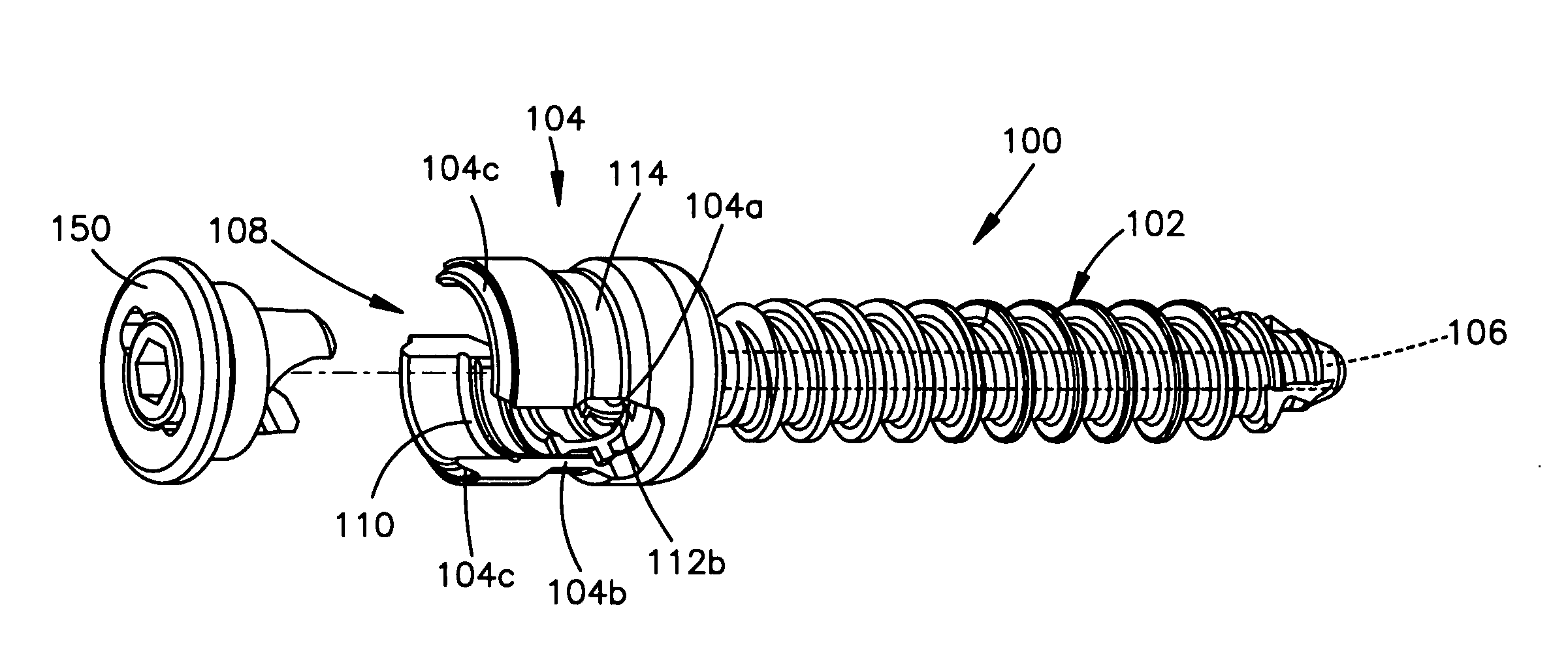
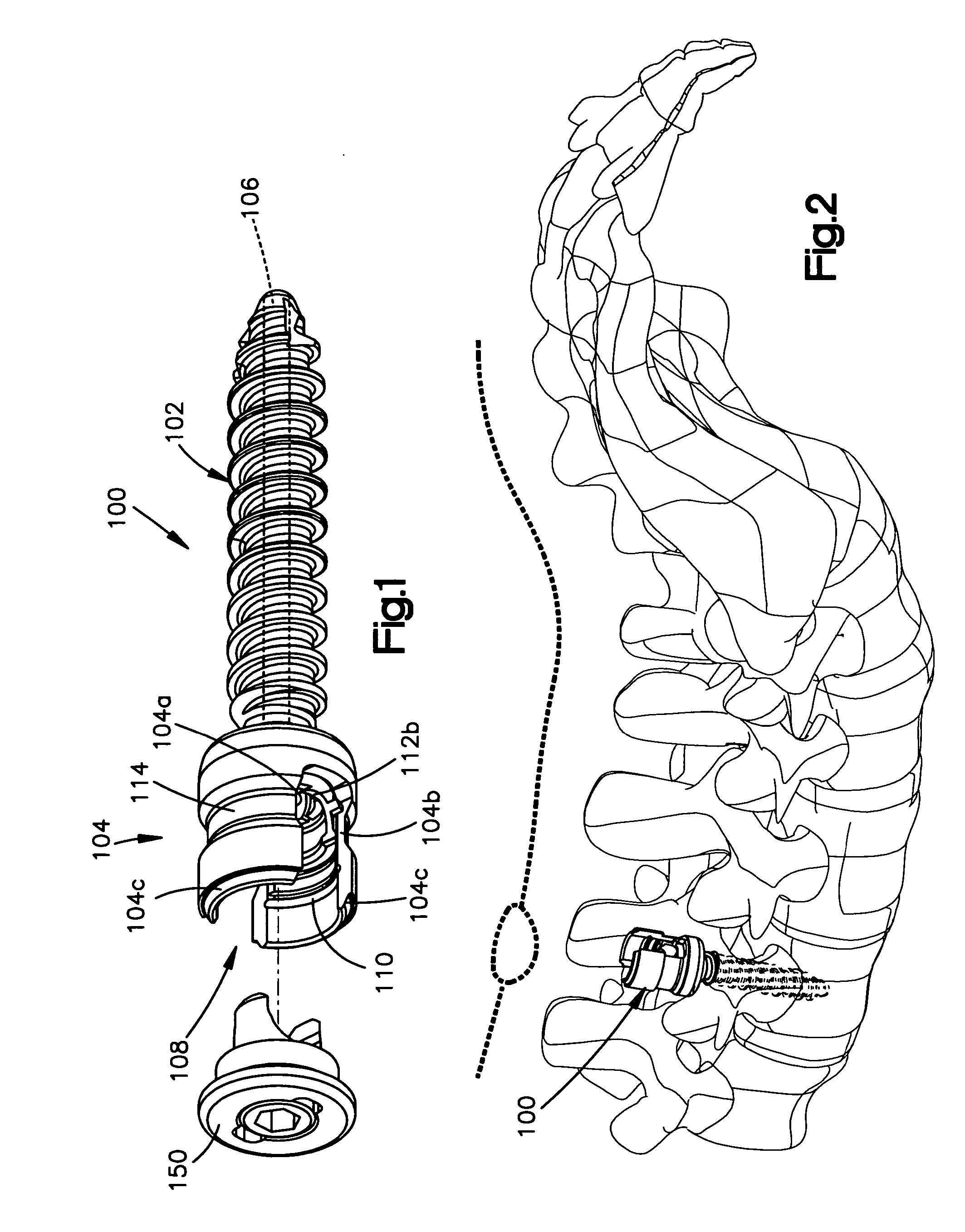
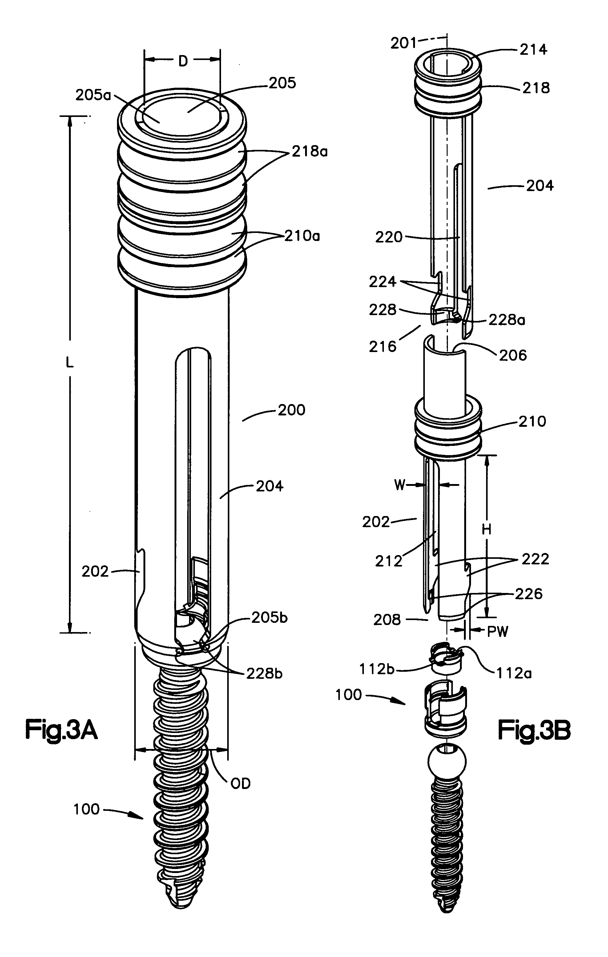
[0080] The method of spinal fixation of the present invention may be performed using various instrumentation, including a plurality of implants (e.g., screws 100), a plurality of insertion guides 200, 300, 350, a sleeve 400, 416, a rod (e.g., a fixation rod 500, 550, 570, 700) and a holding instrument 600, 650, 670, 800. It should, however, be understood that those of ordinary skill in the art will recognize many modifications and substitutions which may be made to various elements of the present invention. Moreover, although the instruments are described herein as being used in connection with spinal fixation procedures, one of ordinary skill in the art will readily appreciate that the instruments may be used in any other parts of the body (e.g., a long bone) to perform a fixation procedure. Thus, the location is not intended to be limiting in any way. In addition, the instruments may be used singularly or in combination with the other instruments described or other instruments tha...


PUM


Abstract

A method for performing spinal fixation and instrumentation. A first incision may be made through the skin and a passageway may be created to the spine. A screw may be inserted through the passageway and into a vertebrae. The screw may have a head portion including a channel. An insertion guide may be operable connected to the screw. The insertion guide may have first and second longitudinal slots. Additional screws may each be inserted through separate incisions or through the first incision. Insertion guides may be operably connected to a head portion of each screw. A sleeve may be positioned into one insertion guide in a first position to guide a rod through at least one other insertion guide. The sleeve may be rotated to a second position to allow the rod to move down the slots of the insertion guide(s) and into the head portion of the screw.

Description

FIELD OF THE INVENTION [0001] The present invention is directed to methods of spinal fixation and, in particular, surgical instruments for performing a minimally invasive spinal fixation procedure. BACKGROUND OF THE INVENTION [0002] Spinal fixation systems which are used to correct spinal deformities and treat spinal degenerations generally consist of a series of bone fasteners anchored in, for example, the pedicle of adjacent vertebra. The bone fasteners are interconnected to one another by one or more elongated spinal rods or plates. In order to access the spinal area for implantation of these spinal fixation systems and their individual components, open approach surgical techniques have traditionally been employed. These open procedures generally involve large skin incisions and extensive tissue retraction and resection, all which may result in considerable post-operative pain and prolonged recovery time. [0003] More recently, surgeons have used minimally invasive techniques to r...

Claims


Application Information

Patent Timeline
IPC IPC(8): A61F2/30A61B17/56A61B17/58
CPCA61B17/7002A61B17/7011A61B17/7037A61B17/7085A61B17/7083A61B17/58A61B17/56A61B17/70
Inventor FRIGG, ROBERTSCHNIDER, MARTINSCHWER, STEFAN
Owner SYNTHES USA
Why Eureka
Eureka Blog
Learn More