
Decoratable utility rod assemblies

a technology of utility rods and components, applied in the field of utility rods and racks, can solve the problems of towel bars or racks being easily loosened and moved around, caps and covers typically require additional structure and attachments, and exposed hollow interiors and the sharp, unattractive ends of rods or racks

Inactive Publication Date: 2007-03-29
NIFTY NOB
View PDF16 Cites 5 Cited by
  • Summary
  • Abstract
  • Description
  • Claims
  • Application Information

AI Technical Summary

Benefits of technology

[0009] The present invention features a simple wall mount that may be screwed to the wall or a stud. A base mount extends outward from the wall mount. The bottom portion of the base is threaded. A cover plate, which may be any shape and decorated in any fashion, has a threaded centr...

Problems solved by technology

Unfortunately, the plates, caps, and covers typically require additional structure and attachments such as set screws, clips, or the like.
If the covers, caps, or plates are not themselves firmly secured, they may detach under use, causing the towel bar or rack to fall from its mount, expose the wall attachment and fasteners, and / or cause the towel bar or rack to loosen and move about when being used.
Due to insecure attachments, end caps for rods and bars may also loosen and fall off, exposing the hollow interior of the rod or rack and the sharp, unattractive ends of the rods or racks.
In addition, such end caps, plates, caps, and covers are usually made of the same materials as are the rods and attachments—i.e., they are made to match the utility rod or rack and do not have the flexibility to easily accommodate different shapes or different designs and / or artwork that may better suit the décor of a room, the interests of the users of the rods or racks, or seasonal themes.
And, many such end caps cannot be changed without removing the rod or rack from the wall.

Method used


Image

  • Decoratable utility rod assemblies
  • Decoratable utility rod assemblies
  • Decoratable utility rod assemblies

Examples


Embodiment Construction

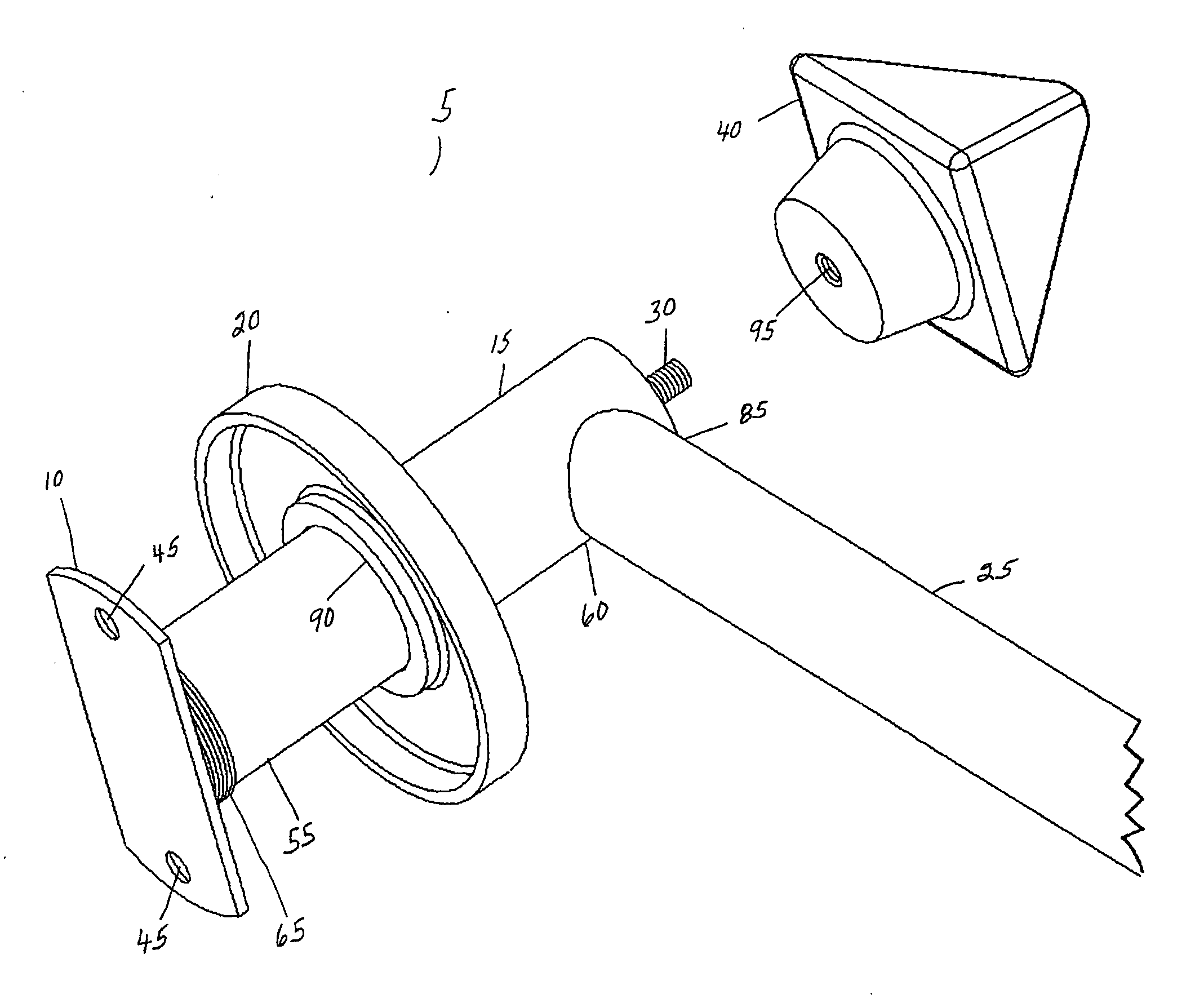
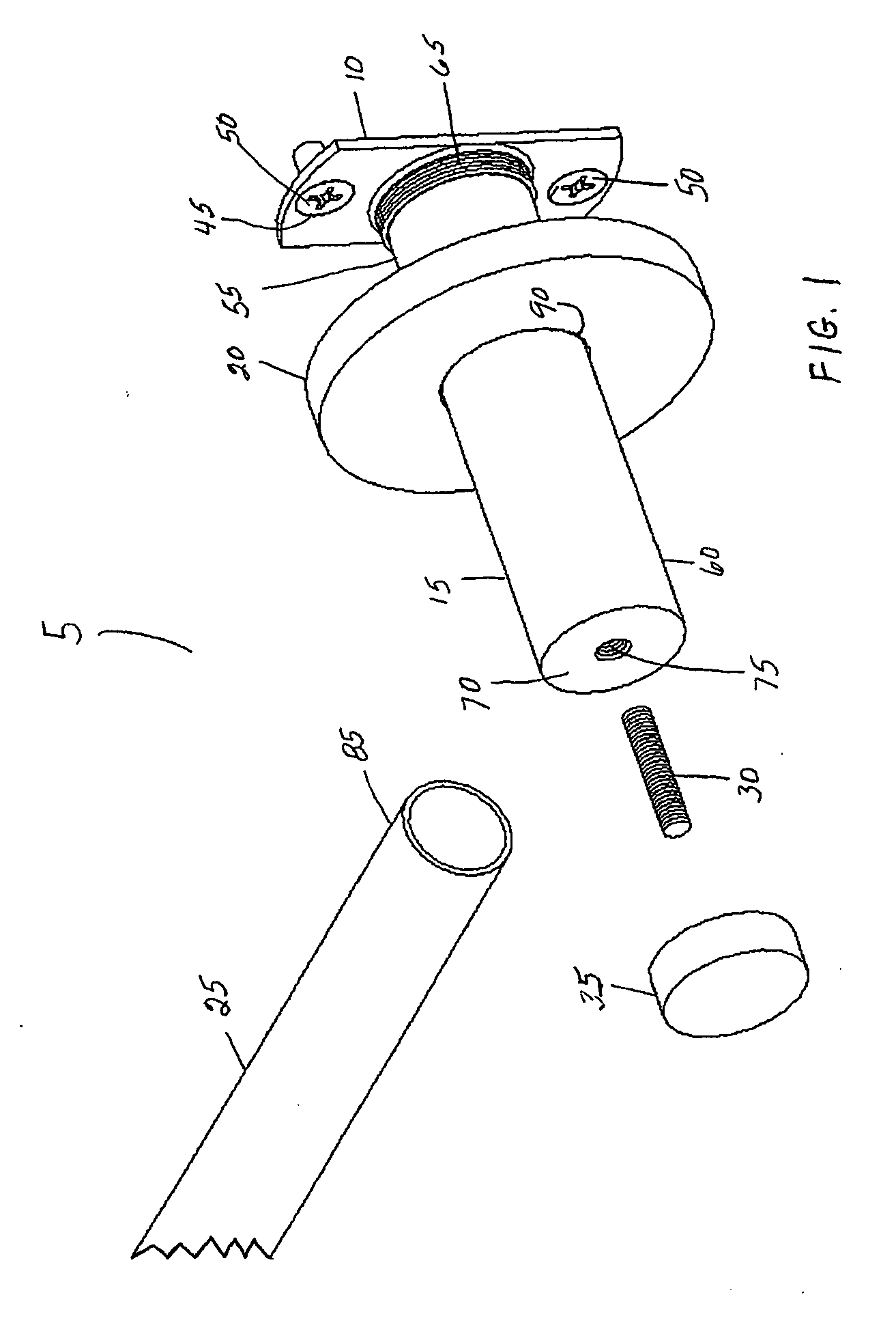
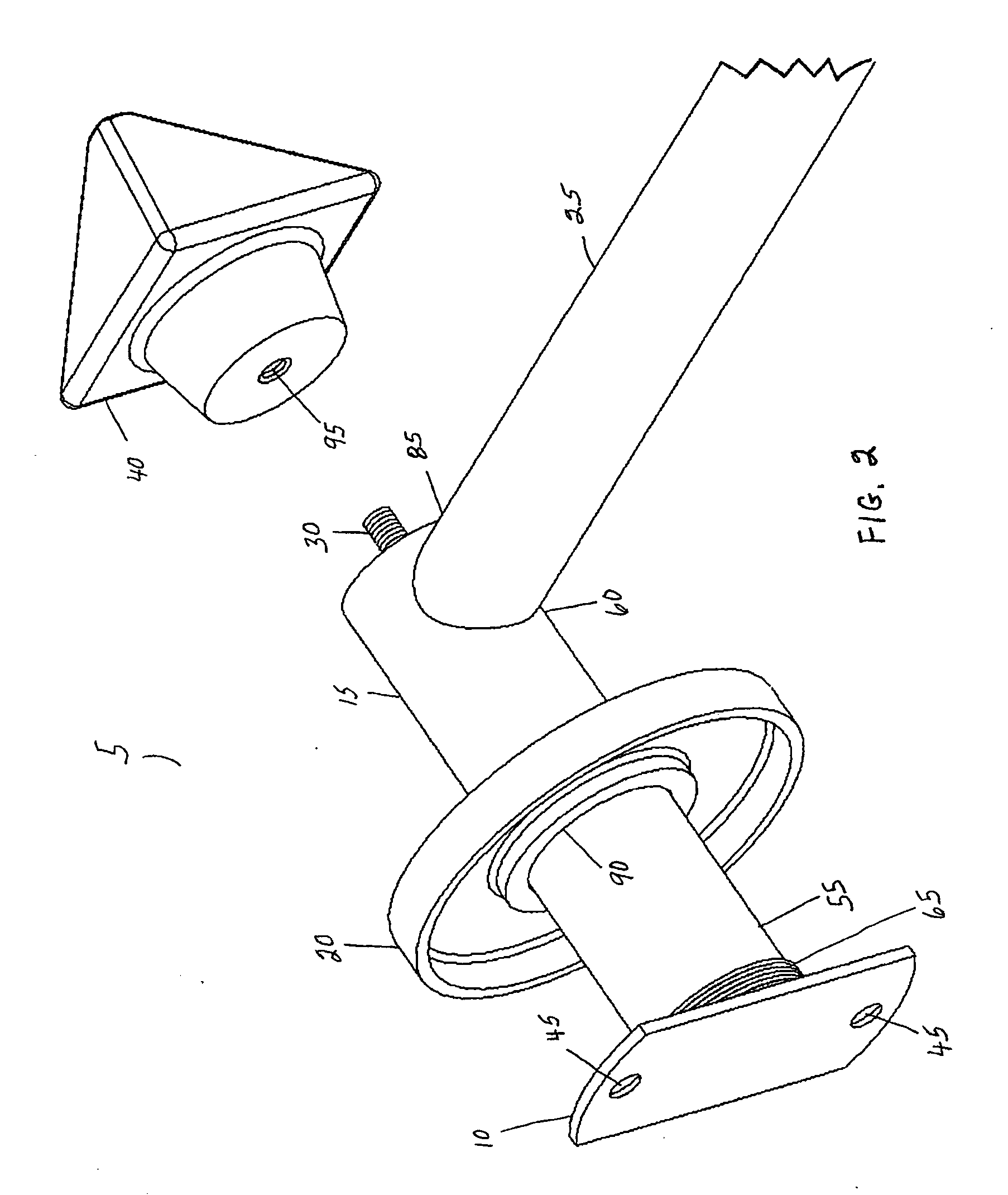
[0027] As shown in FIGS. 1 and 2, the utility rod assembly 5 comprises a wall attachment plate 10, a base rod 15, a cover plate 20, a cross rod 25, a set screw 30, and a knob or end cap 35. FIG. 2 shows the same basic parts, but has a knob or end cap 40 of a different style or shape.

[0028] As shown in FIG. 2, the wall attachment plate 10 contains holes 45 through which the base rod 15 may be secured to a wall or stud (not shown) by screws 50.

[0029] The base rod 15 is incorporated in the attachment plate 10. As shown in FIGS. 1, 3, 4, 5 and 6, a proximal end 55 of the base rod 5 is slightly larger in diameter than the distal end 60 of the base rod 5. As shown in FIGS. 1, 3, and 6, the proximal end 55 of the base rod 5 is threaded, containing threads 65. The distal end 60 of the base rod 5 contains a solid end or plug 70, which forms a threaded hole 75. As shown in FIGS. 3, 5, and 6, the distal end 60 of the base rod 5 also contains a side hole 80 that is sized to receive an end 85 ...


PUM


Abstract

A decorative utility rod assembly that may be attached to a wall or other support surface. The rod assembly has a base rod, a cross rod, a cover plate, a set screw, and a knob or end cap. The proximal (wall) end of the base rod is threaded on its exterior surface. The distal end of the base rod forms a threaded hole. The cover plate forms a threaded hole in a central portion thereof. The cover plate is screwed onto the proximal end of the base rod to hide the wall attachments. One end of set screw is screwed into the threaded hole in the distal end of the base rod. The end cap is screwed onto the other end of the set screw. The cover plate and end cap may be made of a multitude of materials, may have a multitude of surface configurations, may be formed into a multitude of shapes, and may contain indicial of a seasonal, a vanity, an interest of the use, advertising, or decorations to match interior decoration décor. Alternative embodiments include a towel ring, a toilet paper holder, a hook, and shelving.

Description

FIELD OF INVENTION [0001] The field of the invention is utility rods and racks that attach to walls. Specifically, the invention relates utility rods the wall mounts of which may be decorated with streamlined, low profile covers of a variety of shapes that hide screws and other wall attachments and the ends of which may be decorated with knobs, medallions, and end pieces, all of which may be easily changed to match room décor and style, or to conform to a seasonal, interest, or vanity theme. BACKGROUND OF INVENTION [0002] It is common practice to provide utility rods with caps, plates, or other covers to hide the fasteners with which the rods and racks are attached to a wall or other support. Similarly, it is common to provide the ends of rods and racks with caps or plugs that cover the ends of the rods and racks so as to hide the hollow interiors of the rods and racks and cover the exposed, often sharp edges at the ends of the rods and racks. [0003] Unfortunately, the plates, caps,...

Claims


Application Information

Patent Timeline
IPC IPC(8): A47B96/00A47H1/02
CPCA47H1/142A47H2023/003Y10T29/49826Y10T29/49963Y10T29/49947
Inventor ZIMMERMAN, SUSAN C.
Owner NIFTY NOB
Learn More