Eureka AIR delivers breakthrough ideas for toughest innovation challenges, trusted by R&D personnel around the world.

Developer container

a technology for developing containers and toner, applied in the field of developing containers, can solve the problems of excessive supply of toner to the supplying device, difficult regulation of the quantity supplied, and inability to keep the quantity of the discharged toner constan

Inactive Publication Date: 2007-03-15
SHARP KK
View PDF2 Cites 2 Cited by
  • Summary
  • Abstract
  • Description
  • Claims
  • Application Information

AI Technical Summary

Benefits of technology

The invention provides a developer container for an image forming apparatus that can keep the quantity of discharged developer constant. The container includes a supporting member that covers the developer storage space and the discharge hole, and a developer guiding member that guides the developer to the discharge hole. An adhesion eliminating portion is used to eliminate any developer adhering to the guiding member, ensuring constant discharge. The container is designed to prevent narrowing of the discharge hole and maintain the quantity of developer discharged constant. The invention also includes a depressed portion on the inner wall of the container to facilitate the separation of the developer from the guiding member. Overall, the invention provides a simple and effective solution for keeping the developer quantity constant.

Problems solved by technology

Therefore, there is a case where the toner flows out from the opening portion 3 and the toner is excessively supplied to the toner supplying device.
Since there is a need to change the number of rotations of the toner bottle 1 depending on the fill quantity of the toner, there is a problem that it is difficult to regulate the quantity supplied and it is impossible to keep the quantity of the discharged toner constant.
However, each of the configurations has a problem that when the container stops in a state where the through hole 16 or the opening 23 is located below the upper face of the toner, the toner inside the container flows out in large quantities, which leads to a problem that it is impossible to keep the quantity of the discharged toner constant.

Method used


Image

  • Developer container
  • Developer container
  • Developer container

Examples


Embodiment Construction

[0074] Now referring to the drawings, preferred embodiments of the invention are described below.

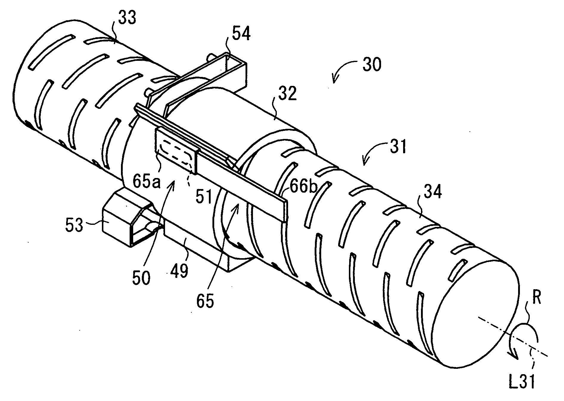
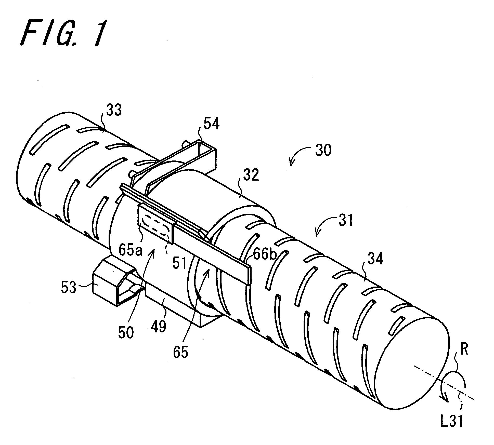
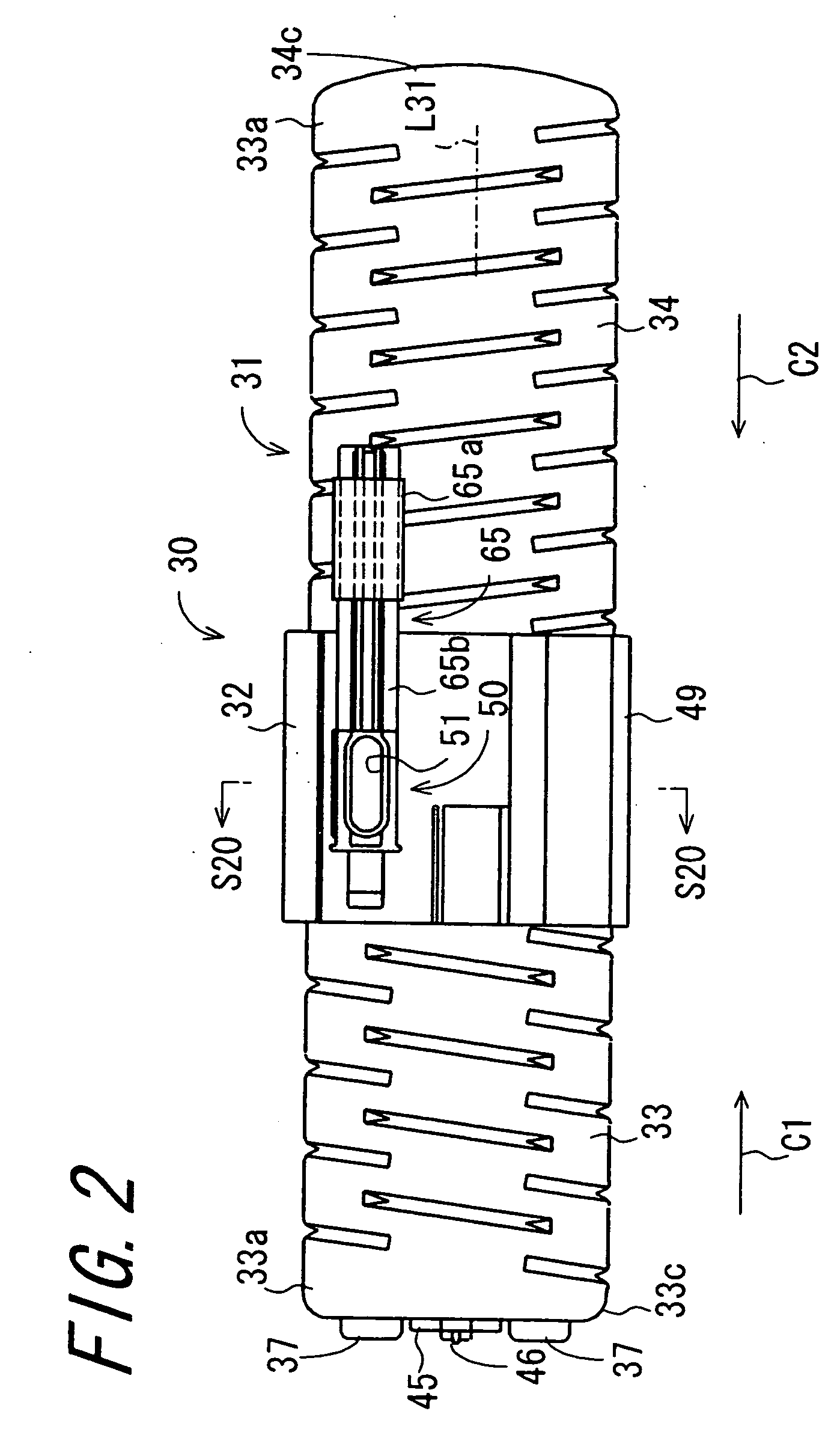
[0075]FIG. 1 is a perspective view illustrating a developer container 30 according to an embodiment of the invention. FIG. 2 is a front view illustrating the developer container 30. FIG. 3 is a left side view illustrating the developer container 30. The developer container 30 comprises a container main body 31 and a supporting member 32. The container main body 31 is formed into a substantially cylindrical shape, and stores toner of a two-component developer such as coloring toner used for electrophotographic image formation, for example. The supporting member 32 supports the container main body 31 so as to be rotatable about an axial line L31 thereof. The developer container 30 is capable of storing, for example, 1400 gram of developer. Hereafter, the axial line L31 of the container main body 31 may be expressed as the rotation axial line L31. In the present embodiment, the container m...


PUM


Abstract

A developer container includes a cylindrical container main body, a supporting member, a sheet-like developer guiding member, and an adhesion eliminating portion. The container main body has a concavity forming a storage space, has a discharge hole, and conveys the stored developer toward the discharge hole by rotating about its axial line. The supporting member covers a portion including the concavity and the discharge hole over circumferences thereof to support the container main body so as to be rotatable about the axial line, and has a leading through hole for leading the developer discharged from the discharge hole of the container main body to the outside. The developer guiding member guides the developer discharged from the discharge hole of the container main body to the leading through hole. The adhesion eliminating portion eliminates developer adhering to the developer guiding member through rotation of the container main body.

Description

BACKGROUND OF THE INVENTION [0001] 1. Field of the Invention [0002] The present invention relates to a developer container that stores a developer used for electrophotographic image formation. [0003] 2. Description of the Related Art [0004]FIGS. 38A and 38B are views illustrating a first related art toner bottle 1. FIG. 38A is a cross section view of the toner bottle 1. FIG. 38B is a perspective view of the toner bottle 1. The toner bottle 1 is formed into a cylindrical shape whose both ends are closed, and has an opening portion 3 formed on one end wall 2 so that a diameter thereof is smaller than a diameter of the cylindrical main body. Part of an inner face of a shoulder portion of an end face 4 on which the opening-portion 3 is formed is made to project from the inner face of the shoulder portion to an edge of the opening portion 3, whereby a projecting portion 5 for lifting toner is formed. An inner face of a periphery wall of the bottle connected to the projecting portion 5 in...

Claims


Application Information

Patent Timeline
Patent Type & Authority Applications(United States)
IPC IPC(8): G03G15/08
CPCG03G2215/067G03G2215/0685G03G15/0877G03G15/0886G03G15/087G03G15/0872
Inventor DEGUCHI, MASANOBUSATOH, TAKESHI
Owner SHARP KK
Why Eureka
Eureka Blog
Learn More