Vapor-emitting device with a solar-powered, active end of use indicator

a technology of active end of use and vapor-emitting device, which is applied in the direction of steam generation using steam absorption, instruments, lighting and heating apparatus, etc., can solve the problem of difficulty in determining how much volatilized material there is

Inactive Publication Date: 2007-03-15
DIAL CORPORATION
View PDF6 Cites 15 Cited by
  • Summary
  • Abstract
  • Description
  • Claims
  • Application Information

AI Technical Summary

Problems solved by technology

There are, however, at least a few problems associated with such a requirement, 1) users must remember that it is nearing the time and / or time to replace / refill the vapor-emitting device; 2) users must personally inspect the vapor-emitting device and / or refill to determine if it is nearing the time and / or time to replace / refill the vapor-emitting device; and 3) upon inspection, users must have the capability of determining that indeed the vapor-emitting device contains a low amount of volatizable material and / or is no longer emitting vapor, which may be difficult if the volatizable material is not readily visible and / or leaves a residue making it difficult to determine how much, if any, volatizable material remains.

Method used


Image

  • Vapor-emitting device with a solar-powered, active end of use indicator
  • Vapor-emitting device with a solar-powered, active end of use indicator
  • Vapor-emitting device with a solar-powered, active end of use indicator

Examples


Embodiment Construction

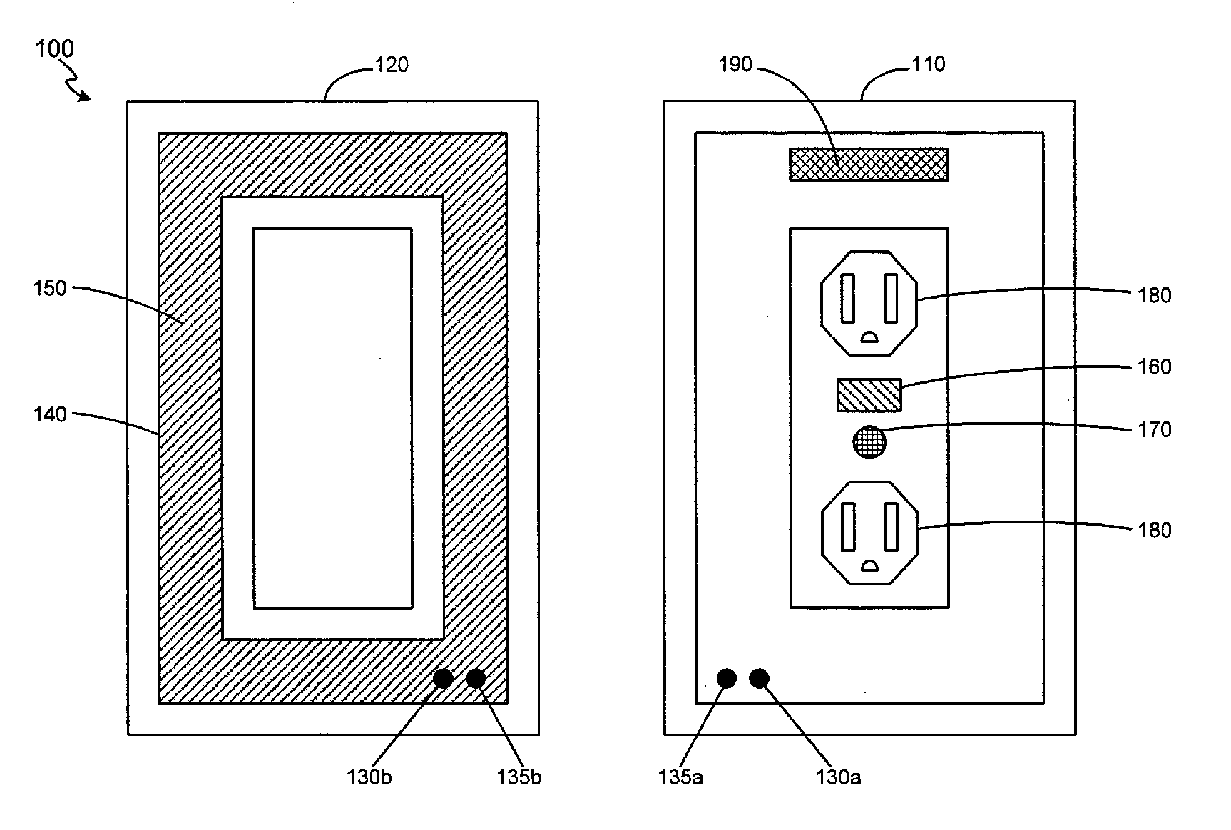
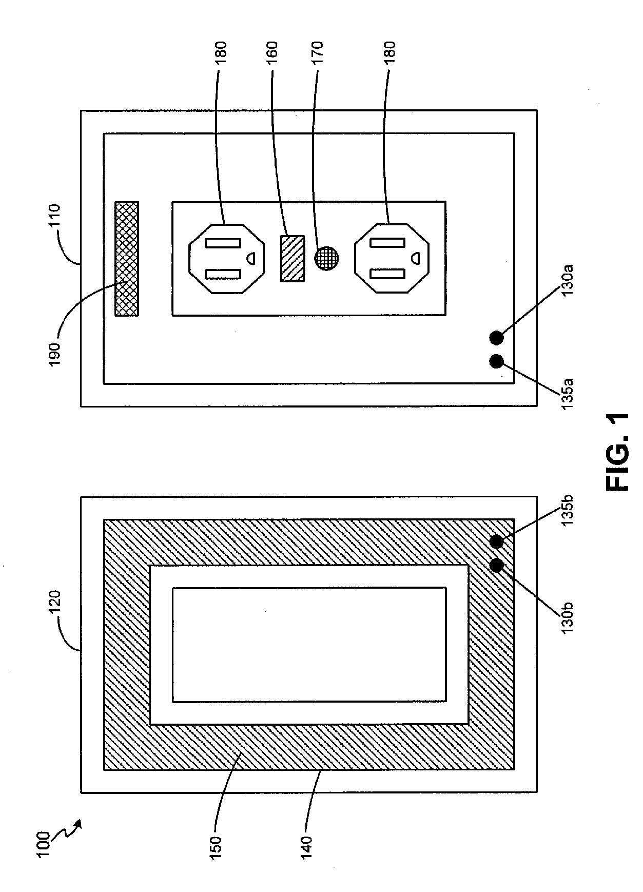
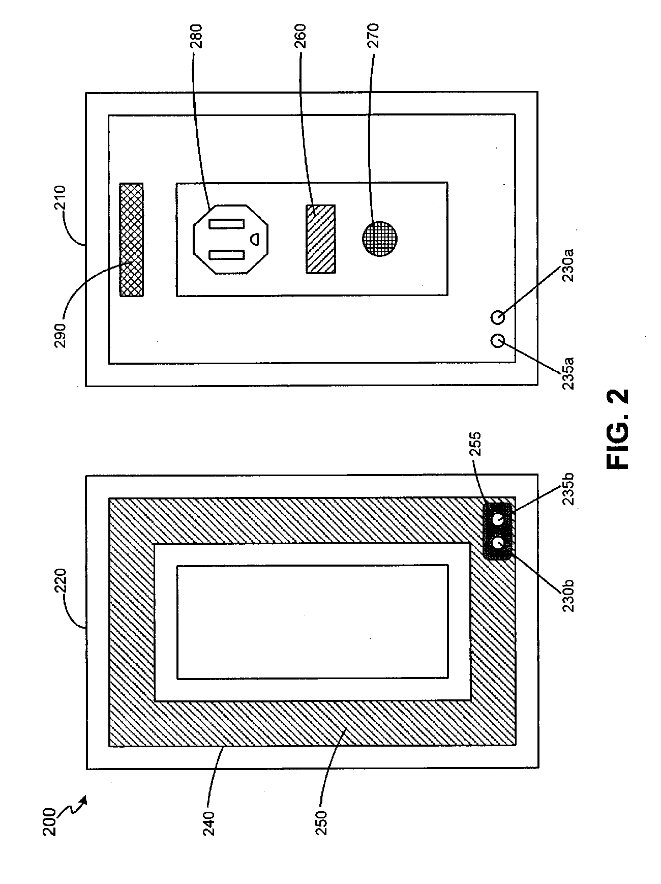
[0016] The detailed description of exemplary embodiments of the invention herein makes reference to the accompanying figures, which show the exemplary embodiment by way of illustration and its best mode. While these exemplary embodiments are described in sufficient detail to enable one skilled in the art to practice the invention, it should be understood that other embodiments may be realized, and that logical and / or mechanical changes may be made without departing from the spirit and scope of the invention. Thus, the detailed description herein is presented for purposes of illustration only and not by way of limitation.

[0017] For the sake of brevity, functional embodiments of the apparatus and systems (and components of the individual operating components of the systems) may not be described in detail herein. Furthermore, the connecting lines shown in the various figures contained herein are intended to represent exemplary functional relationships and / or physical connections betwe...


PUM

PropertyMeasurementUnit
non-conductiveaaaaaaaaaa
spherical shapeaaaaaaaaaa
conductiveaaaaaaaaaa

Abstract

Vapor-emitting devices according to various embodiments of the invention include active end of use indicators to warn users that it is nearing the time and / or time to replace the vapor-emitting device or a refill for the device. Some embodiments of the vapor-emitting devices include intrusive actuation of the end of use indicator, while other embodiments include non-intrusive actuation of the end of use indicator. The indicators may be visual and / or auditory cues for notifying users it is nearing the time and / or time to replace the vapor-emitting device or a refill for the device.

Description

CROSS-REFERENCE TO RELATED APPLICATIONS [0001] This application is a continuation of, and claims the benefit of co-pending U.S. application Ser. No. 11 / 162,519, filed Sep. 13, 2005.FIELD OF INVENTION [0002] The invention generally relates to vapor-emitting devices, and particularly to, vapor-emitting devices including an active end of use indicator. BACKGROUND OF INVENTION [0003] Vapor-emitting devices are generally used to emit an environment-altering fragrance, an insect repellant, and / or the like. Typically, to know when it is time to replace the vapor-emitting device or a refill for the vapor-emitting device, users are required to take the initiative to visually inspect the contents and / or refill of the vapor-emitting device. There are, however, at least a few problems associated with such a requirement, 1) users must remember that it is nearing the time and / or time to replace / refill the vapor-emitting device; 2) users must personally inspect the vapor-emitting device and / or ref...

Claims


Application Information

Patent Timeline
Patent Type & Authority Applications(United States)
IPC IPC(8): A61L9/03
CPCA01M1/2044A61L9/037A61L9/127G01F23/22G01F23/223H01H35/18G01F23/2921G01F23/44G01F23/70G01F23/74G01F23/241
Inventor BANKERS, PHD, JEFFREYKAISER, PERRYHAFER, KEVIN
Owner DIAL CORPORATION
Why Eureka
Try Eureka