
Shoe pad structure having an air chamber

a technology of air chamber and shoe pad, which is applied in the direction of shoes, top-pieces, heels, etc., can solve the problems of increasing the cases of injury during exercise or sporting activities, and the large compression force of the user's heels, so as to achieve a better buffer effect and prevent injury

Inactive Publication Date: 2007-03-15
TSAI SHUANG CHU
View PDF4 Cites 28 Cited by
  • Summary
  • Abstract
  • Description
  • Claims
  • Application Information

AI Technical Summary

Benefits of technology

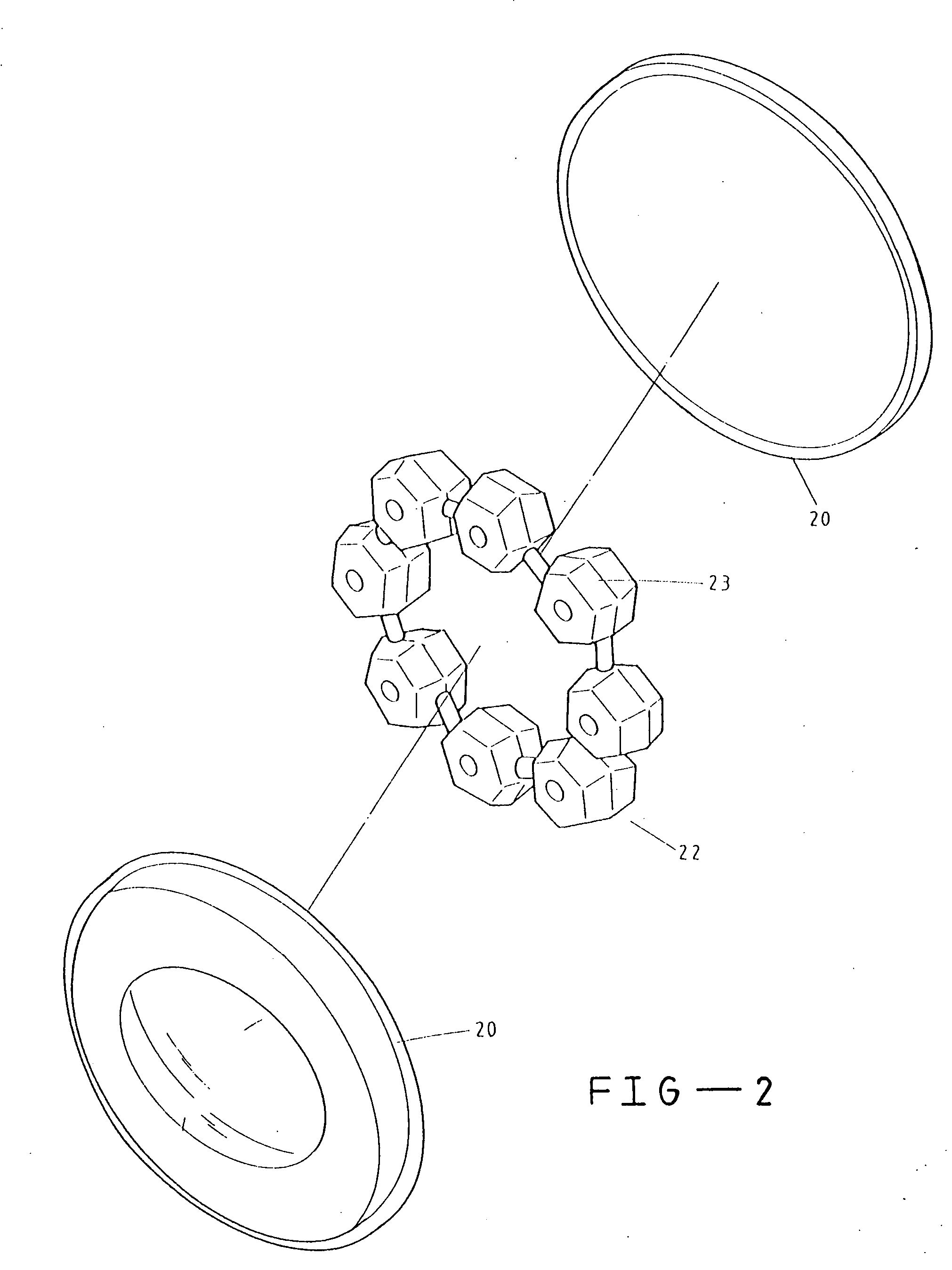
[0008] The objective of the present invention is to provide a type of shoe pad structure having an air chamber with a buffer effect and applicable to the heel or ball on a shoe sole, comprising of a flexible unit installed in an air chamber composed of two flexible plastic films having slightly depressed centers, particularly the flexible unit is installed in the center depression of the air chamber, forming a ring-shaped buffer air chamber at the rim of the flexible unit in the air chamber, thereby providing better buffer effect, to prevent injury during sports and exercise activities.

Problems solved by technology

As a result, it has become a fad for people to engage in sports or exercise, which has resulted in increasing cases of injury during exercise or sporting activities.
Most injuries sustained during exercise or sport are caused by either insufficient warm-up or poorly designed sports shoes.
As a result, when the user jumps up and down on a surface, it produces a large compression force from the user's heels.

Method used


Image

  • Shoe pad structure having an air chamber
  • Shoe pad structure having an air chamber
  • Shoe pad structure having an air chamber

Examples


Embodiment Construction

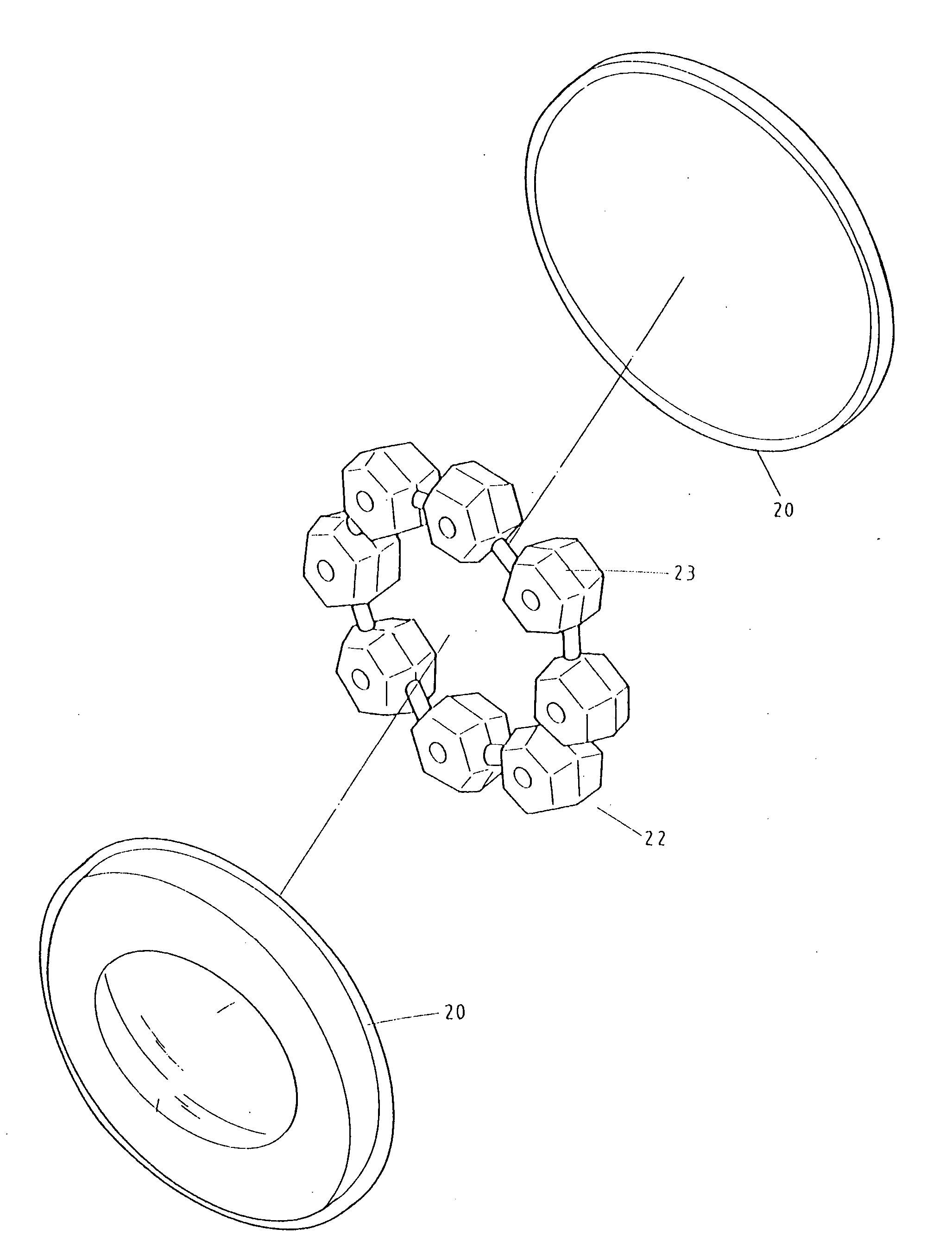
[0015] Please refer to FIGS. 2 to 4. The present invention is a shoe pad structure having an air chamber, particularly a shoe pad structure having an air chamber providing buffer function, applicable to the heel or ball of a shoe sole, comprising an air chamber 21 consisting of two flexible plastic films 20 with slightly depressed center parts, containing a flexible unit 22. The flexible unit 22 is a flexible plastic block 23, or a serial combination of more than one flexible plastic block 23. The flexible unit 22 is installed in the center depression of the air chamber 21, forming a ring-shaped buffer air chamber 24 at the rim of the flexible unit 22 in the air chamber 21.

[0016] Because of the special structural design of the present invention as described above, the present invention has the following characteristics in application: [0017] 1. Because of the present invention of shoe pad structure, the flexible unit 22 is installed at a central depression of the air chamber 21, fo...


PUM


Abstract

A shoe pad structure having an air chamber, particularly a shoe pad structure having an air chamber with cushion effects and applicable to the heel or ball on a shoe sole, comprising a flexible unit installed in an air chamber composed of two flexible plastic films with depressed centers thereof, characterized in that: the flexible unit is installed in the center depression of the air chamber, forming a ring-shaped buffer air chamber at the rim of the flexible unit in the air chamber, thereby enabling better cushion effects to prevent possible injury from exercise.

Description

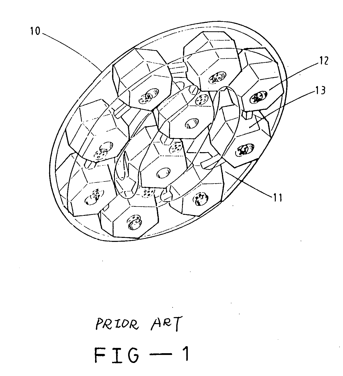
BACKGROUND OF THE INVENTION [0001] 1. Field of the Invention [0002] The present invention relates to a shoe pad structure having an air chamber, particularly a shoe pad structure having an air chamber with cushion effects and applicable to the heel or ball on a shoe sole. [0003] 2. Description of the Prior Art [0004] Due to better living standards in recent years, people have placed an increasing emphasis on their physical health. As a result, it has become a fad for people to engage in sports or exercise, which has resulted in increasing cases of injury during exercise or sporting activities. Most injuries sustained during exercise or sport are caused by either insufficient warm-up or poorly designed sports shoes. Insufficient warm-up can be corrected by the person doing the exercise, but poor design of sports shoes will have to be addressed by manufacturers. To date, the shoe industry has spent an extended period of time researching a design to prevent injury during sports activit...

Claims


Application Information

Patent Timeline
Patent Type & Authority Applications(United States)
IPC IPC(8): A43B13/20A43B21/28
CPCA43B1/0009A43B21/28A43B13/20
Inventor TSAI, SHUANG-CHU
Owner TSAI SHUANG CHU
Learn More