
Apparatus and method for controlling recording signals

a recording signal and apparatus technology, applied in the field of optical disc recording apparatuses, can solve the problems of data loss, data loss, data loss, etc., and achieve the effect of quick stabilization of the recording signal

Inactive Publication Date: 2007-03-08
SAMSUNG ELECTRONICS CO LTD
View PDF1 Cites 2 Cited by
  • Summary
  • Abstract
  • Description
  • Claims
  • Application Information

AI Technical Summary

Benefits of technology

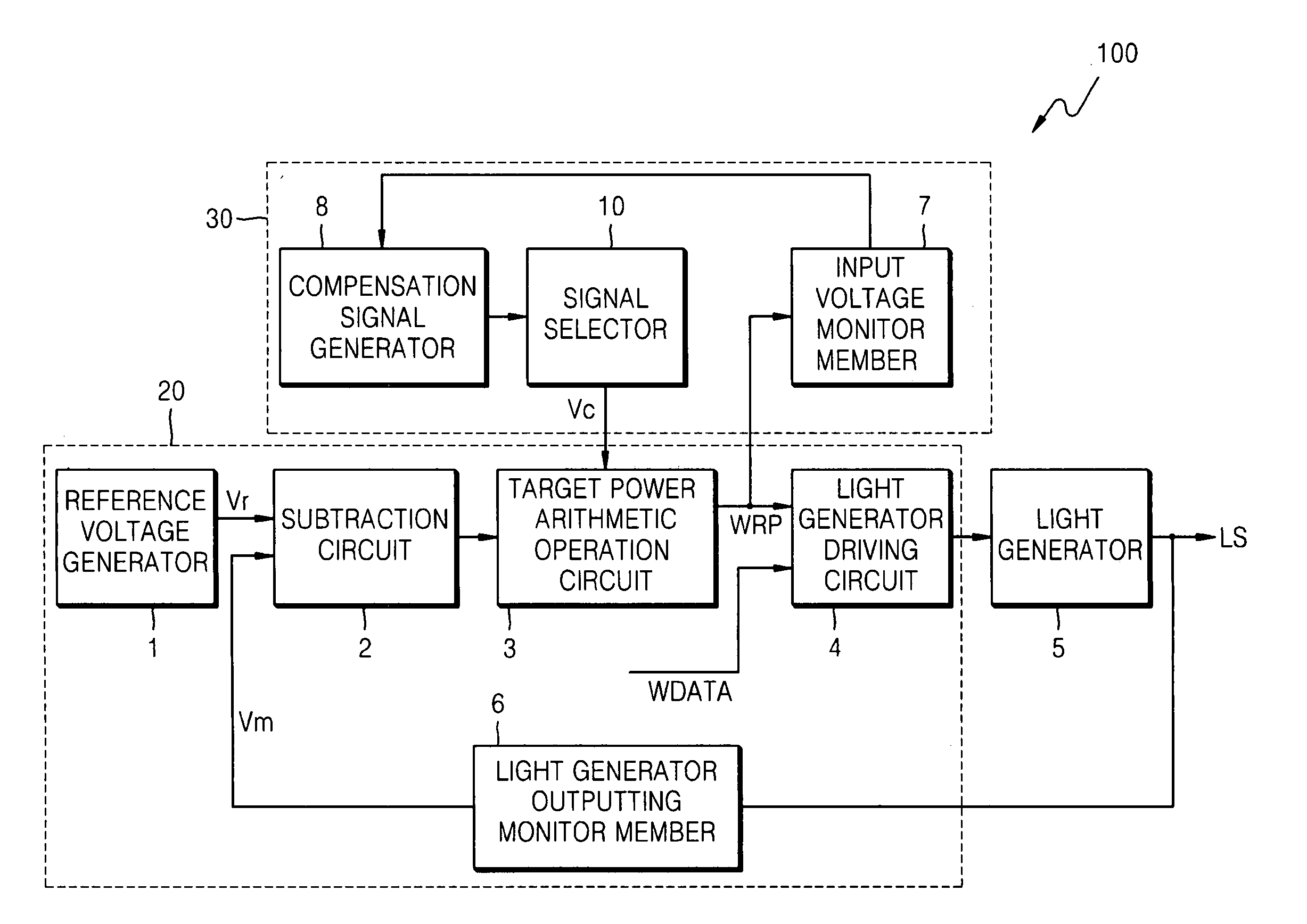
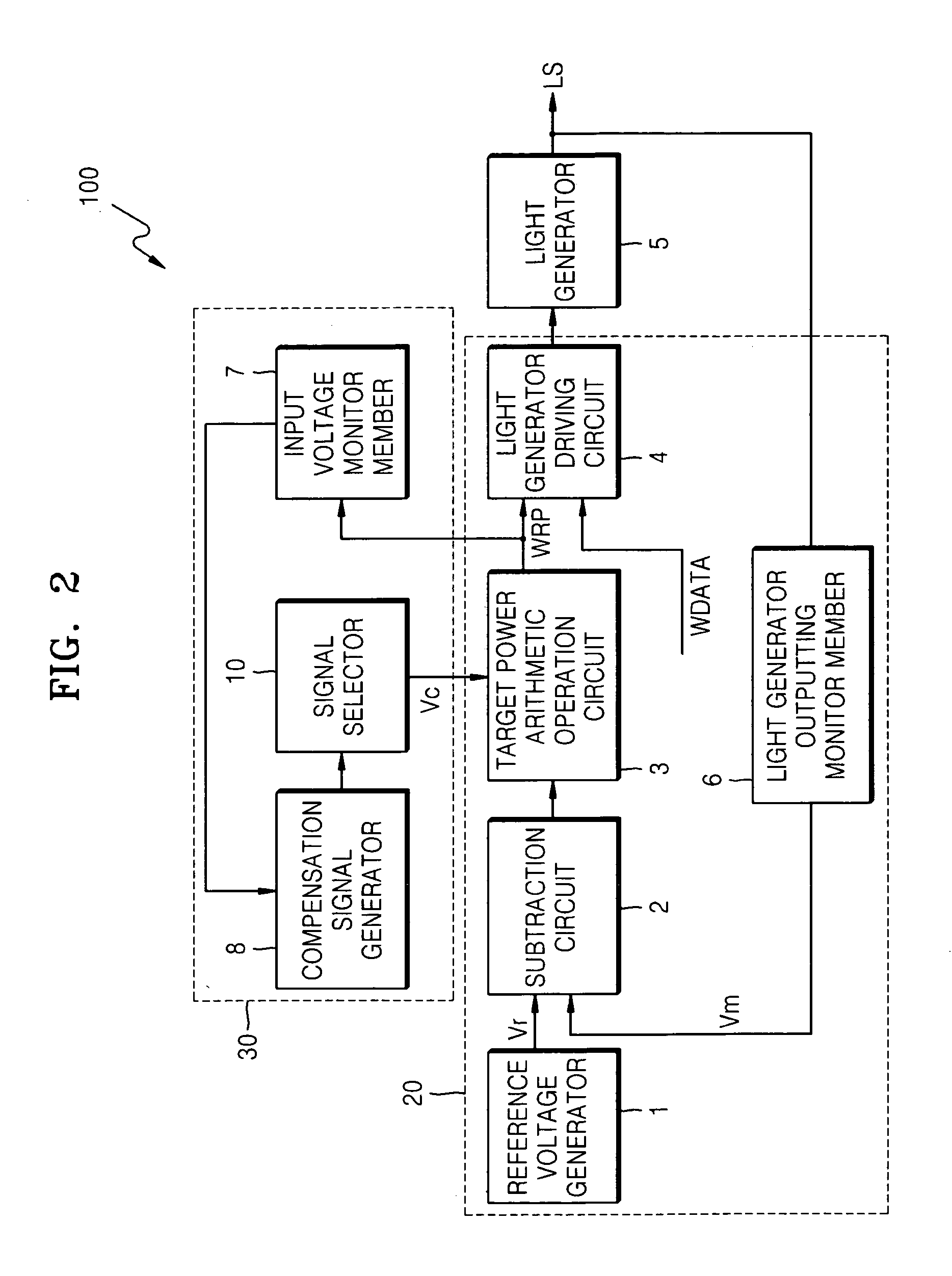
[0014] Example embodiments provide an apparatus for controlling a recording signal that more quickly stabilizes the recording signal during an initial write operation.
[0015] Example embodiments also provide a method of controlling a recording signal that more quickly stabilizes the recording signal during an initial write operation.

Problems solved by technology

If an optical disk recording apparatus stops writing due to buffer underrun, insecure servo signals, wobble quality, contamination, changes in recording speeds, and / or external shocks, during a write operation, normal recording results may not be obtained.
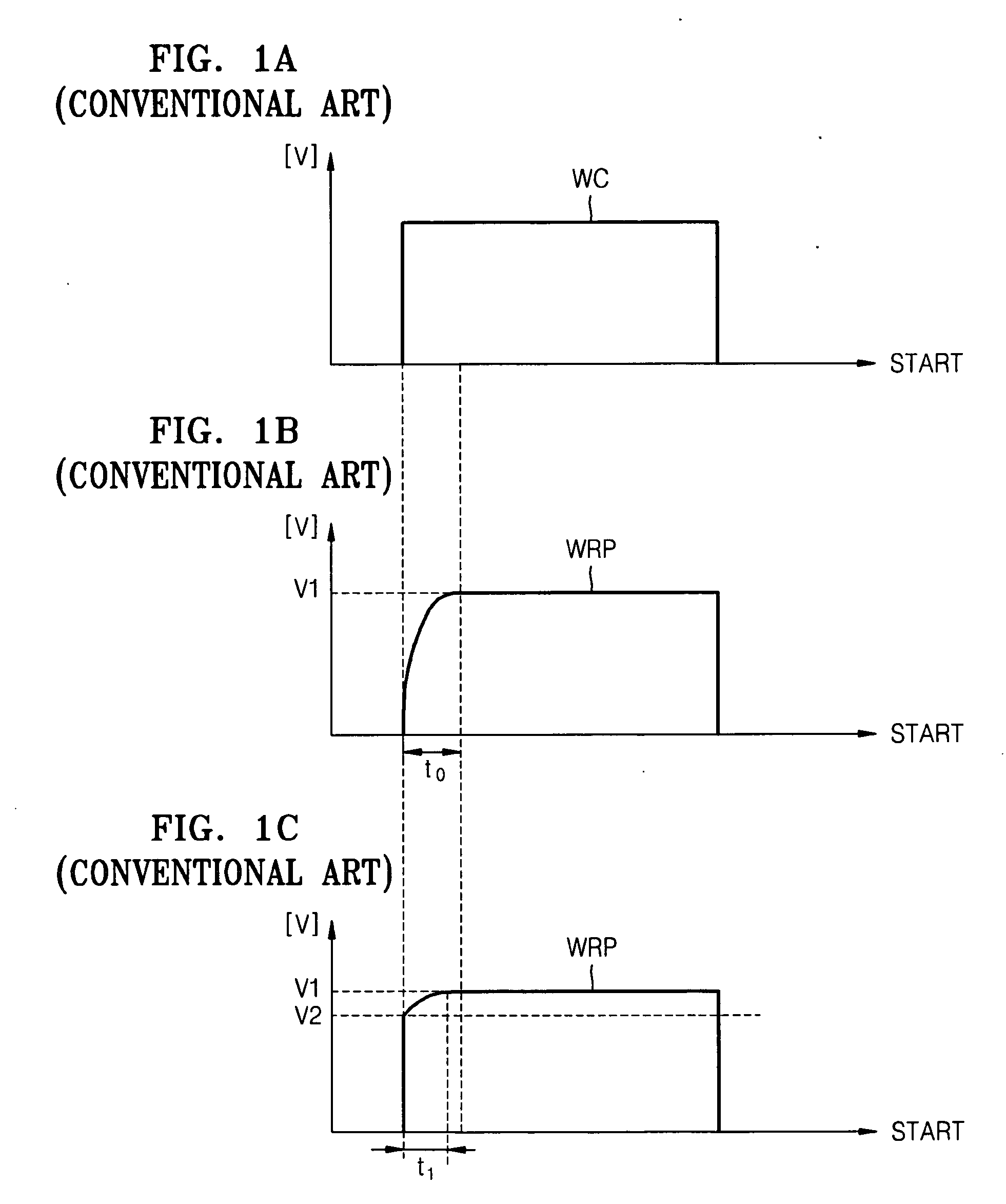
Because the optical disk recording apparatus does not perform a write operation during a period of time t0 due to lack of a reference voltage required to write data, data loss may occur.
However, such a method may cause data loss during an initial predetermined or given period of time t1 after the conventional apparatus for controlling the recording signal controls the write mode.
Also, because the optical disk recording apparatus may perform the write operation at a relatively high speed, the optical disk recording apparatus may write more data during the initial predetermined or given period of time ti than before, and more data loss may occur.

Method used


Image

  • Apparatus and method for controlling recording signals
  • Apparatus and method for controlling recording signals
  • Apparatus and method for controlling recording signals

Examples


Embodiment Construction

[0025] Various example embodiments are described more fully hereinafter with reference to the accompanying drawings, in which example embodiments are shown. Example embodiments may, however, be embodied in many different forms and should not be construed as limited to example embodiments set forth herein. Rather, these example embodiments are provided so that this disclosure will be thorough and complete and will fully convey the scope of example embodiments to those skilled in the art. In the drawings, the sizes and relative sizes of layers and regions may be exaggerated for clarity.

[0026] It will be understood that when an element or layer is referred to as being “on,”“connected to” or “coupled to” another element or layer, it can be directly on, connected or coupled to the other element or layer or intervening elements or layers may be present. In contrast, when an element is referred to as being “directly on,”“directly connected to” or “directly coupled to” another element or l...


PUM

PropertyMeasurementUnit
voltage levelaaaaaaaaaa
voltageaaaaaaaaaa
energyaaaaaaaaaa

Abstract

An apparatus and method for controlling a recording signal are provided. The apparatus may include a light generator generating light used to write information to an optical disk, a light amount compensator setting a voltage level of the recording signal as a second level when the write operation is performed or stopped, and a light amount controller supplying energy to the light generator based on the second level of the recording signal until the voltage level of the recording signal reaches a first level when a rewrite operation is started and controlling the light generated by the light generator to be constant after the voltage level of the recording signal reaches the first level. The apparatus and method for controlling the recording signal may reduce write quality deterioration due to a lack of initial power of the recording signal when an optical disk recording apparatus starts a rewrite operation after stopping a write operation due to buffer underrun, insecure servo signals, wobble quality, contamination of discs, changes in recording speeds, and / or external shocks.

Description

PRIORITY STATEMENT [0001] This application claims the benefit of Korean Patent Application No. 10-2005-0081993, filed on Sep. 03, 2005, in the Korean Intellectual Property Office, the disclosure of which is incorporated herein in its entirety by reference. BACKGROUND [0002] 1. Field [0003] Example embodiments relate to an optical disc recording apparatus, for example, to an apparatus for controlling a recording signal that stabilizes a recording signal during an initial write operation, and a method of performing the same. [0004] 2. Description of the Related Art [0005] An optical disk recording apparatus records data onto discs such as compact disc (CD), digital versatile disc (DVD), blu-disc (BD), or high definition (HD)-DVD or reproduces data recorded on such a disc. [0006] If an optical disk recording apparatus stops writing due to buffer underrun, insecure servo signals, wobble quality, contamination, changes in recording speeds, and / or external shocks, during a write operation...

Claims


Application Information

Patent Timeline
Patent Type & Authority Applications(United States)
IPC IPC(8): G11B7/00G11B7/125
CPCG11B7/1263G11B7/0045
Inventor KIM, SOO-YONGCHO, SEUNG-ICK
Owner SAMSUNG ELECTRONICS CO LTD
Learn More