Apparatus and method for determining type of an optical disk
- Summary
- Abstract
- Description
- Claims
- Application Information
AI Technical Summary
Problems solved by technology
Method used
Image
Examples
first embodiment
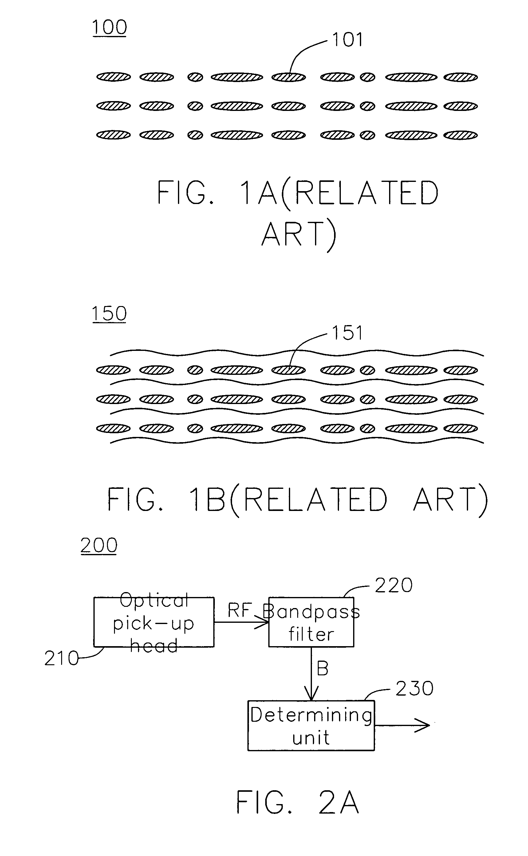
[0022]FIG. 2A is a block diagram of an optical disk drive according to the invention. The optical disk drive 200 determines the type of an optical disk according to whether a wobble signal is detected. The optical disk drive 200 includes an optical pick-up head 210, a bandpass filter 220 and a determining unit 230. The optical pick-up head 210 is for reading an optical disk and outputting a radio frequency signal RF. The bandpass filter 220 filters the radio frequency signal RF to output a bandpass signal B. Next, the determining unit 230 determines whether the bandpass signal B corresponds to the wobble signal. If so, it indicates that the optical disk has a spiral groove and is a recordable optical disk; otherwise, the optical disk is a read-only optical disk.
[0023] The determining unit 230 determines whether the bandpass signal B corresponds to the wobble signal according to the frequency spectrum or the period of the bandpass signal B.
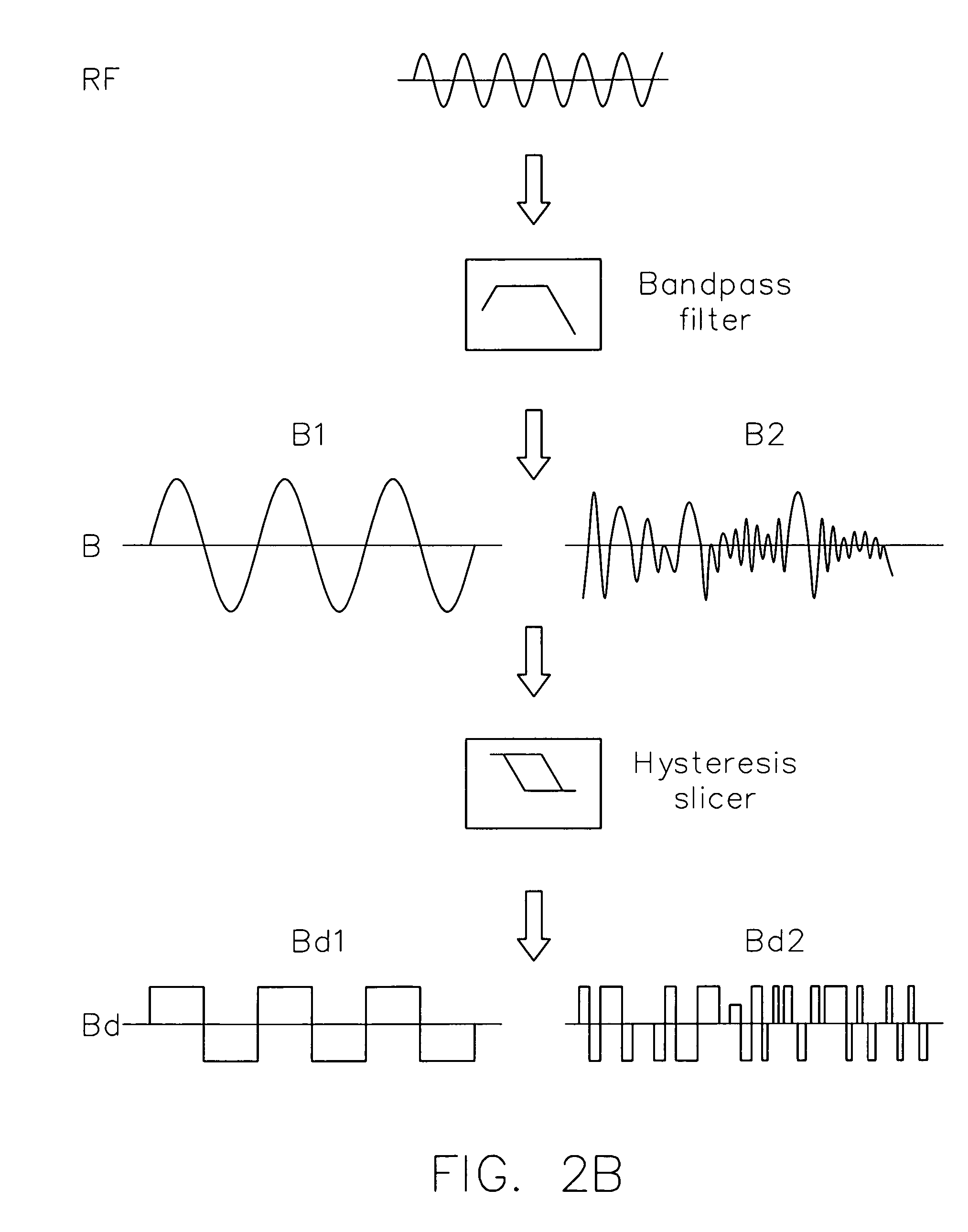
[0024] Referring to FIG. 2B, a waveform dia...
second embodiment
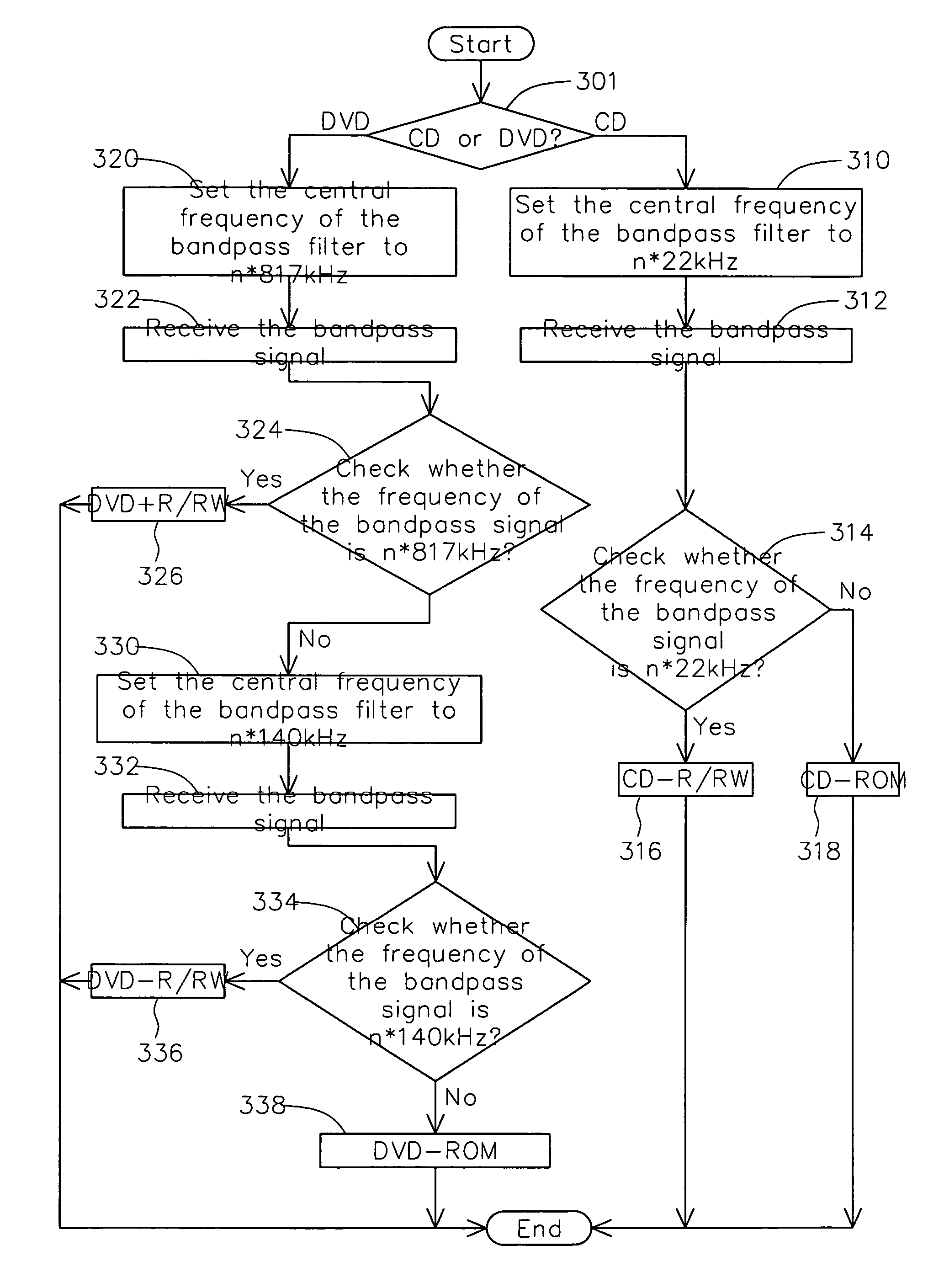
[0027]FIG. 3 is a flowchart for a method of determining the type of an optical disk according to the invention. Firstly, the method begins at step 301 in order to determine whether the optical disk is a CD or a DVD. If the optical disk is a CD, the method proceeds to step 310. If the optical disk is a DVD, the method proceeds to step 320. In step 310, the central frequency of the bandpass filter 220 is set to n*22 kHz, wherein n indicates the optical disk drive operating at n times a single speed for the optical disk drive. Next, the bandpass signal B outputted by the bandpass filter 220 is received, as indicated in step 312. Then, step 314 is performed to determine whether a frequency component n*22 kHz dominates the frequency components of the bandpass signal B. If so, the bandpass signal B is a wobble signal; that is, the optical disk has a spiral groove and is a recordable optical disk CD-R / RW (step 316). Otherwise, the optical disk is a read-only CD (step 318).
[0028] In the ste...
third embodiment
[0033]FIG. 5 is a flowchart for a method of determining the type of an optical disk according to the invention. Firstly, the method begins at step 501, whether the optical disk is a CD or a DVD is determined. If the optical disk is a CD, the method proceeds to step 510. Otherwise, the method proceeds to step 520 if the optical disk is a DVD. In step 510, the central frequency of the bandpass filter 220 is sequentially set to Hc, Hc+δ, Hc+2δ, and Hc+3δ, and the corresponding bandpass signals Ba, Bb, Bc, and Bd outputted by the bandpass filter 220 are received, wherein Hc is n*22 kHz, n indicates the optical disk drive operating at n times a single speed for the optical disk drive, and the offset value δ is n*1 kHz for instance. Next, in step 512, it is determined whether I(Ba)+I(Bb)>I(Bc)+I(Bd). If so, the optical disk has a spiral groove and is determined to be a recordable optical disk CD-R / RW (step 514); otherwise, the optical disk is a read-only CD (step 516). It is noted that in...
PUM
 Abstract
Description
Claims
Application Information
 - R&D
- Intellectual Property
- Life Sciences
- Materials
- Tech Scout
- Unparalleled Data Quality
- Higher Quality Content
- 60% Fewer Hallucinations
Browse by: Latest US Patents, China's latest patents, Technical Efficacy Thesaurus, Application Domain, Technology Topic, Popular Technical Reports.
© 2025 PatSnap. All rights reserved.Legal|Privacy policy|Modern Slavery Act Transparency Statement|Sitemap|About US| Contact US: help@patsnap.com


