Manufacturing a mirror plate or other operational structure having superior flatness by laser milling for use with torsional hinged devices

a technology of laser milling and mirror plate, which is applied in the direction of mountings, microelectromechanical systems, instruments, etc., can solve the problems of ineffective spines, affecting the flatness of mirror reflective surfaces, and affecting the flatness of smaller and even thinner mirrors with even greater rotational speeds

Active Publication Date: 2007-03-08
TEXAS INSTR INC
View PDF1 Cites 4 Cited by
  • Summary
  • Abstract
  • Description
  • Claims
  • Application Information

AI Technical Summary

Benefits of technology

[0011] As stated above, the front level shape, and truss level shape of the multilevel structure form a single unitary or integral piece of material, such as for example a silicon substrate layer or wafer having a selected thickness. The mirror plate or silicon substrate layer or wafer includes one or more areas where the mirror plate or multilevel structure will be formed. Although the method of the invention is intended to include the manufacture of a single mirror plate or other superior multilevel structure, preferably the process is used to manufacture a plurality of such devices that are formed in one or more silicon wafers. According to the invention, the back side of a silicon layer such as for example a silicon wafer is laser milled in at least one area and preferably a plurality of areas to remove silicon material according to a first pattern. The silicon material may also be removed to one or more selected depth levels. These one or more depth levels are less than the thickness of the silicon layer. Removal of the silicon material from the at least one area forms...

Problems solved by technology

However, as the demand for higher print speeds and better resolution increases, flatness of the mirror reflective surface becomes a much more serious problem.
In addition, smaller and even thinner mirrors with even greater rotational speeds are also affected by flexing modes around the mirror edges during high speed operations.
Unfortunately a hinge plate alone with center spines simply is not effective to assure the necessary flatness or to sufficiently reduce the various types of flexing.
Of course, the oscillating member, the hinge plate or mirror itself can be made thicker, but this increases the weight ...

Method used


Image

  • Manufacturing a mirror plate or other operational structure having superior flatness by laser milling for use with torsional hinged devices
  • Manufacturing a mirror plate or other operational structure having superior flatness by laser milling for use with torsional hinged devices
  • Manufacturing a mirror plate or other operational structure having superior flatness by laser milling for use with torsional hinged devices

Examples


Embodiment Construction

[0028] The presently preferred embodiments are discussed in detail below. It should be appreciated, however, that the present invention provides many applicable inventive concepts that can be embodied in a wide variety of specific contexts. The specific embodiments discussed are merely illustrative of specific ways to make and use the invention, and do not limit the scope of the invention.

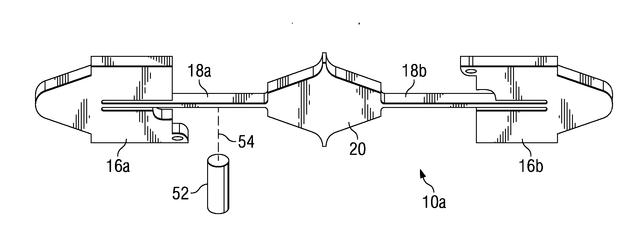
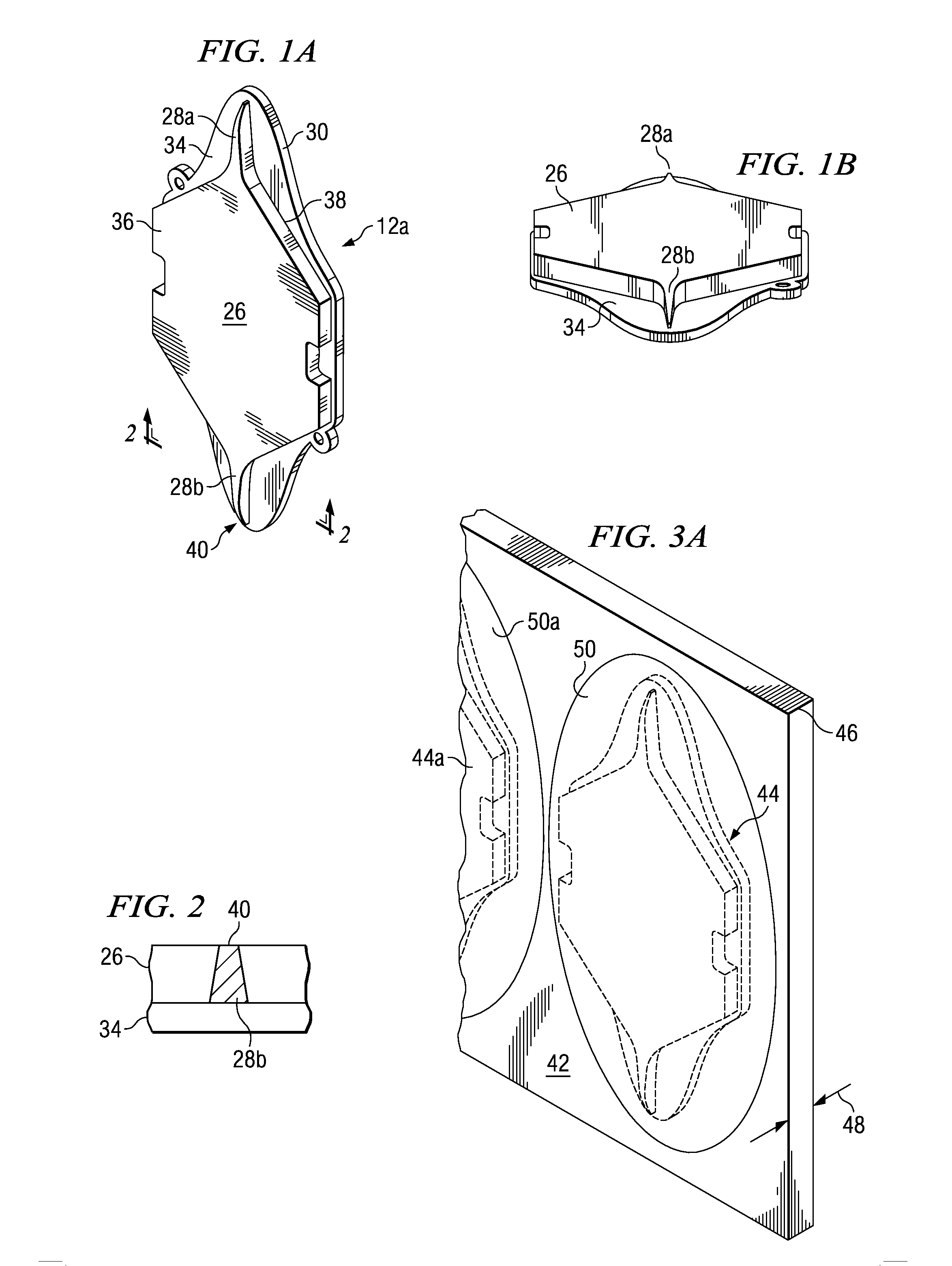
[0029] Referring now to FIGS. 1A and 1B, there is shown two perspective back views of a multilevel structure mirror formed according to the teachings of the present invention. The multilevel mirror structure is suitable for use as a component of a torsional hinged oscillating mirror, such as for example, a resonant mirror. As can be seen from FIGS. 1A and 1B, the multilevel mirror structure 12a is similar to the mirror shape discussed in the prior art FIGS. 8C and 8D. As shown, there is a first level shape or truss structure 26 formed integral with a mirror level or second level shape 34 that defi...


PUM


Abstract

A multilevel mirror plate suitable for use with a torsional hinged mirror assembly is laser milled to provide a more effective truss structure in less time and at a reduced cost.

Description

[0001] This application claims the benefit of U.S. Provisional Application No. 60 / 658,228, filed on Mar. 2, 2005, entitled Manufacturing Silicon Torsional Optical Devices Utilizing Laser Milling, which application is hereby incorporated herein by reference. CROSS-REFERENCE TO RELATED APPLICATIONS [0002] This application relates to the following co-pending and commonly assigned patent applications: Ser. No. ______(TI-60682), filed concurrently herewith, entitled Method Of Adjusting The Resonant Frequency Of An Assembled Torsional Hinged Device, which application is hereby incorporated herein by reference.TECHNICAL FIELD [0003] The present invention relates to the manufacture of a multilevel mirror plate or other multilevel operational structures for use with torsional hinged devices that rotate or oscillate at high speeds, and more particularly to manufacturing such structures or mirror by laser milling that have superior flatness to similar mirrors manufactured by other techniques. ...

Claims


Application Information

Patent Timeline
IPC IPC(8): G02B7/182
CPCB81B3/0067G02B26/0833B81B2201/042
Inventor ORCUTT, JOHN W.DEWA, ANDREW STEVENTURNER, ARTHUR MONROE
Owner TEXAS INSTR INC
Why Eureka
Try Eureka