Dipole antenna

a dipole antenna and antenna technology, applied in the direction of resonant antennas, antenna supports/mountings, radiating elements structural forms, etc., can solve the problems of inability to meet the miniaturization trend of current electrical devices, the inability of radio transmission systems to transmit and receive data, and the inability to effectively reduce etc., to achieve the effect of reducing the dimension of dipole antennas, reducing the application product of dipole antennas, and reducing the trend of miniaturization

Inactive Publication Date: 2007-03-08
ARCADYAN
View PDF5 Cites 2 Cited by
  • Summary
  • Abstract
  • Description
  • Claims
  • Application Information

AI Technical Summary

Benefits of technology

[0009] As mentioned above, the third radiating part of the first radiating member and the first and second radiating parts of the first radiating member are on opposite surfaces, and the sixth radiating part of the second radiating member and the fourth and fifth radiating parts of the second radiating member are disposed on opposite surfaces. Thus, it is possible to effectively reduce the dimension of the dipole antenna, such that the application product of the dipole antenna may be minimized, and the trend of miniaturized electrical devices can be met.

Problems solved by technology

If the antenna is lost, the radio transmission system cannot transmit and receive data.
However, if the conventional dipole antenna wants to reach the better polarization effect, its dimension cannot be effectively reduced, and the product dimension has to be increased and cannot meet the miniaturization trend of the current electrical device.

Method used


Image

  • Dipole antenna
  • Dipole antenna
  • Dipole antenna

Examples


Embodiment Construction

[0017] The present invention will be apparent from the following detailed description, which proceeds with reference to the accompanying drawings, wherein the same references relate to the same elements.

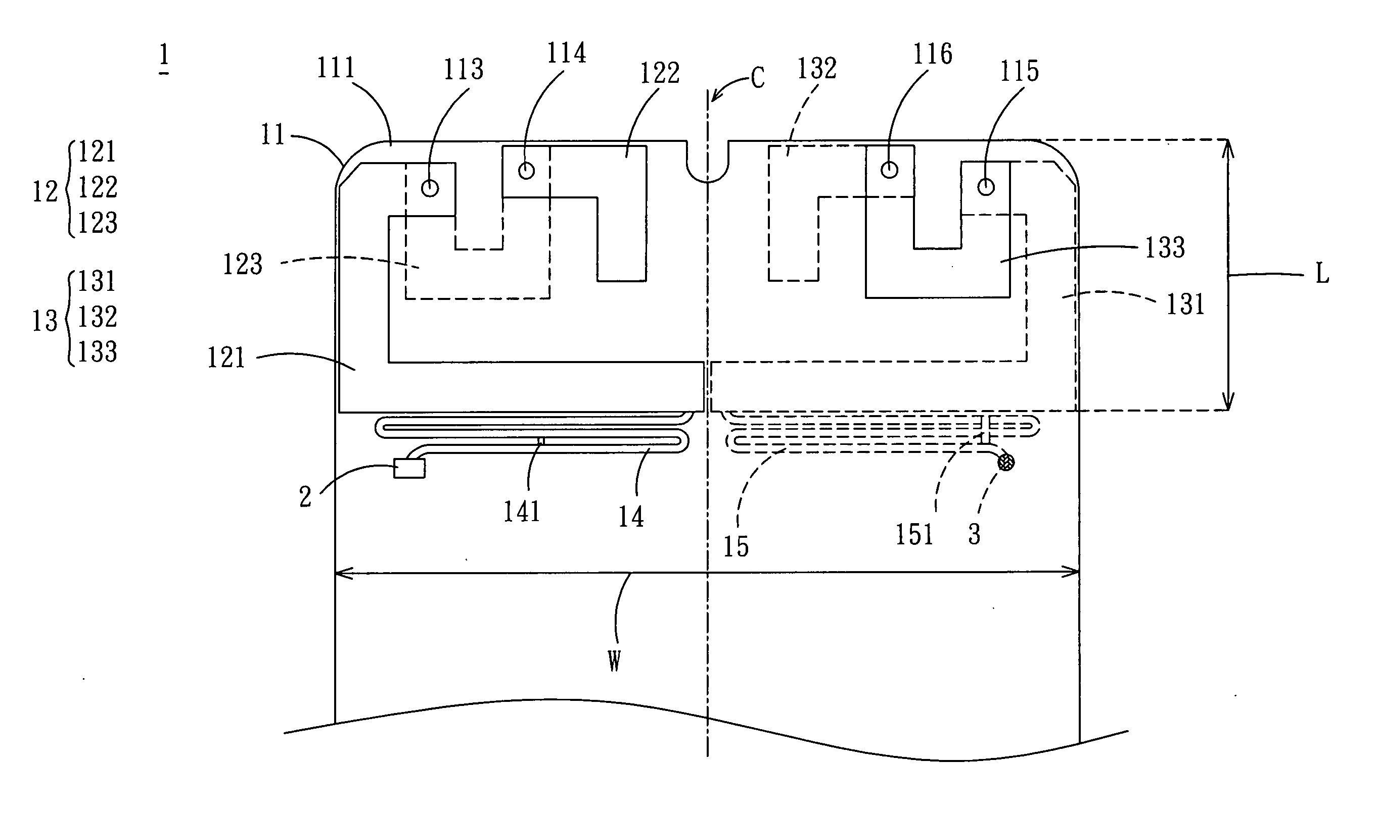
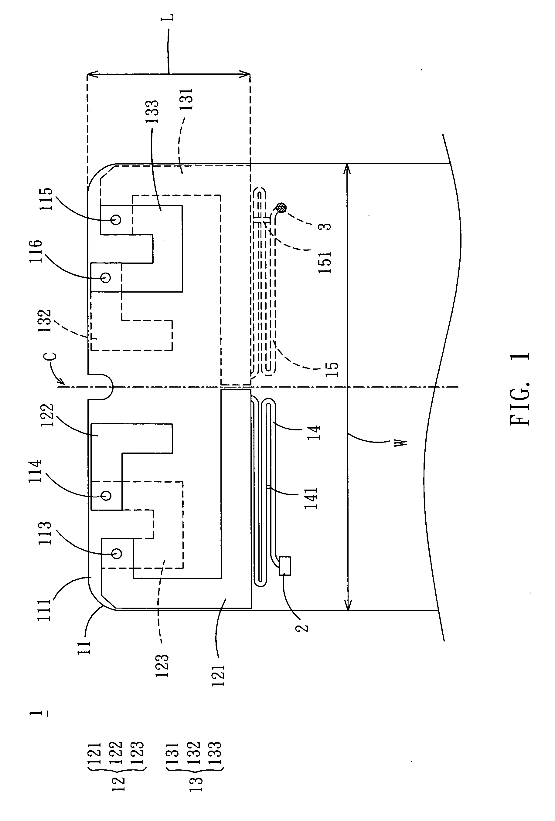
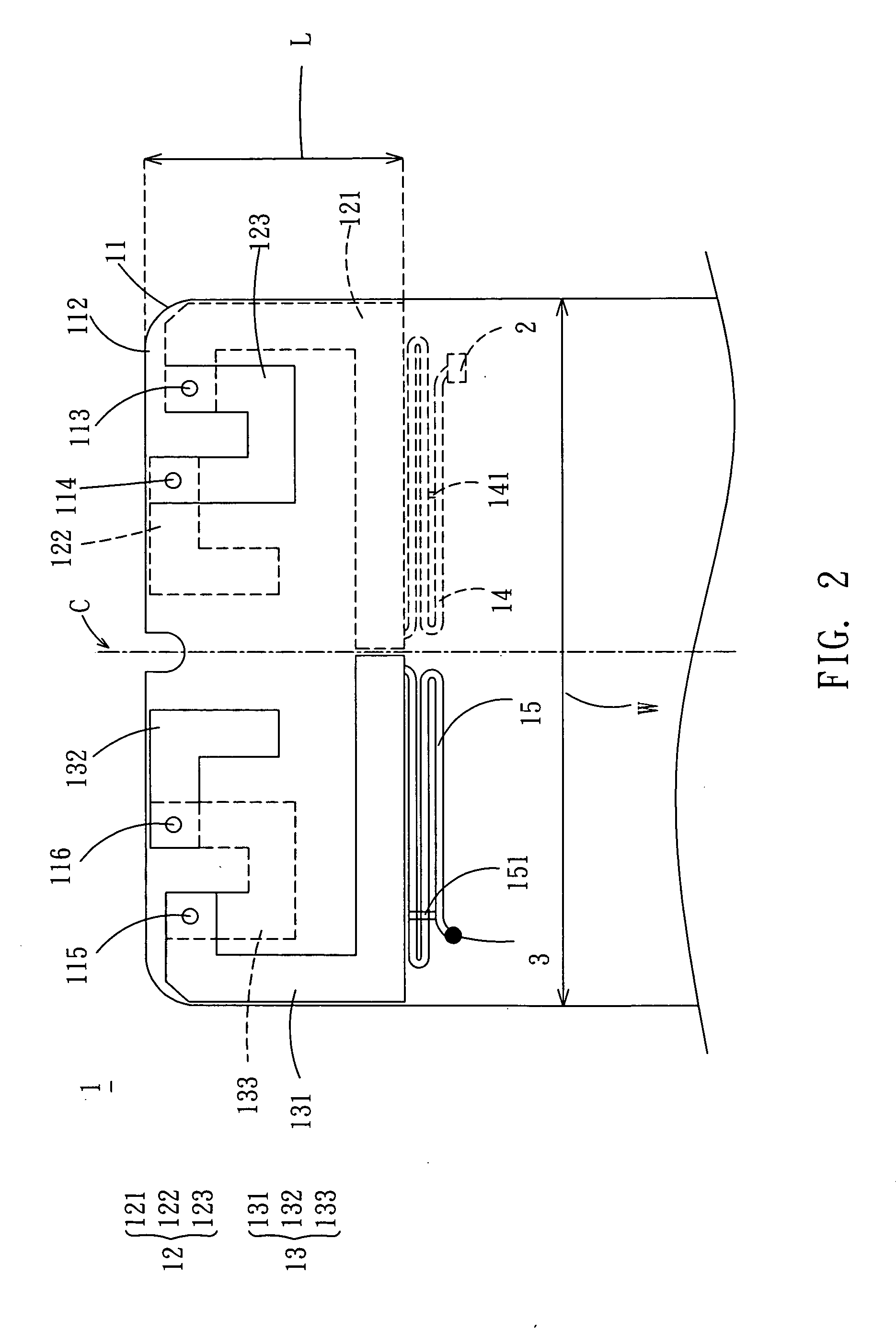
[0018] Referring to FIGS. 1 and 2, a dipole antenna 1 according to the preferred embodiment of the invention includes a substrate 11, a first radiating member 12 and a second radiating member 13. The first radiating member 12 and the second radiating member 13 are symmetrically disposed on the substrate 11 with a center axis C serving as a symmetrical axis. The dipole antenna 1 may have a length L ranging from about 0.6 cm to 0.9 cm, and a width W ranging from about 1.5 cm to 2.3 cm.

[0019] The substrate 11 has a first surface 111, a second surface 112, a first through hole 113, a second through hole 114, a third through hole 115 and a fourth through hole 116. The first surface 111 and the second surface 112 are opposite to each other. In this embodiment, the material of the substra...


PUM


Abstract

A dipole antenna includes a substrate, a first radiating member and a second radiating member. The substrate has a first surface and a second surface opposite to the first surface. The first radiating member and the second radiating member are symmetrically disposed on the first surface and the second surface of the substrate, and electrically connected to a grounding point and a feeding point, respectively. The first radiating member has a first radiating part, a second radiating part and a third radiating part, which are respectively disposed on the first surface and the second surface of the substrate and electrically connected to one another. The second radiating member has a fourth radiating part, a fifth radiating part and a sixth radiating part, which are respectively disposed on the first surface and the second surface of the substrate and are electrically connected to one another.

Description

BACKGROUND OF THE INVENTION [0001] 1. Field of Invention [0002] The invention relates to an antenna, and more particularly to a dipole antenna with an effectively reduced dimension. [0003] 2. Related Art [0004] The rapidly developed radio transmission has brought various products and technologies applied in the field of multi-band transmission, such that many new products have the performance of radio transmission to meet the consumer's requirement. The antenna is an important element for transmitting and receiving electromagnetic wave energy in the radio transmission system. If the antenna is lost, the radio transmission system cannot transmit and receive data. Thus, the antenna plays an indispensable role in the radio transmission system. Selecting a proper antenna can match the feature of the product, enhance the transmission property, and further reduce the product cost. Different methods and different materials for manufacturing the antennas are used in different application pr...

Claims


Application Information

Patent Timeline
Patent Type & Authority Applications(United States)
IPC IPC(8): H01Q9/28
CPCH01Q9/26H01Q1/22
Inventor LEE, CHANG-JUNG
Owner ARCADYAN
Why Eureka
Try Eureka