
Energy dampening system and an element therefore

a dampening system and energy technology, applied in the direction of reactive armor, containers preventing decay, transportation and packaging, etc., can solve the problems of wasted energy of an impinging shaped charge or kinetic head caused by detonation of a sandwiched layer of explosive material in a cassette, and achieve the effect of preventing or minimizing sympathetic initiation

Inactive Publication Date: 2007-02-22
THE STATE OF ISRAEL MINIST OF AGRI & RURAL DEV AGRI RES ORG ARO VOLCANI CENT
View PDF11 Cites 34 Cited by
  • Summary
  • Abstract
  • Description
  • Claims
  • Application Information

AI Technical Summary

Benefits of technology

[0022] The arrangement is such that the energy / impact imparted to an outside wall of the protected body / structure by the mass of a moving plate of the armor cassette is significantly lower. This may be of significant importance for protection of relatively thin wall structures, e.g. a door of a vehicle (personnel door or service door), where deformation thereof may result in dis-functioning thereof.
[0023] Thus, the system according to the present invention acts in two aspects, namely preventing or minimizing sympathetic initiation and

Problems solved by technology

Energy of an impinging shaped charge or a kinetic head or blast caused by detonation of a sandwiched layer of explosive material in a cassette is wasted over mutual mechanical deformation of a moving metal plate of the cassette and of the associated cavitated dampening plate.

Method used


Image

  • Energy dampening system and an element therefore
  • Energy dampening system and an element therefore
  • Energy dampening system and an element therefore

Examples


Embodiment Construction

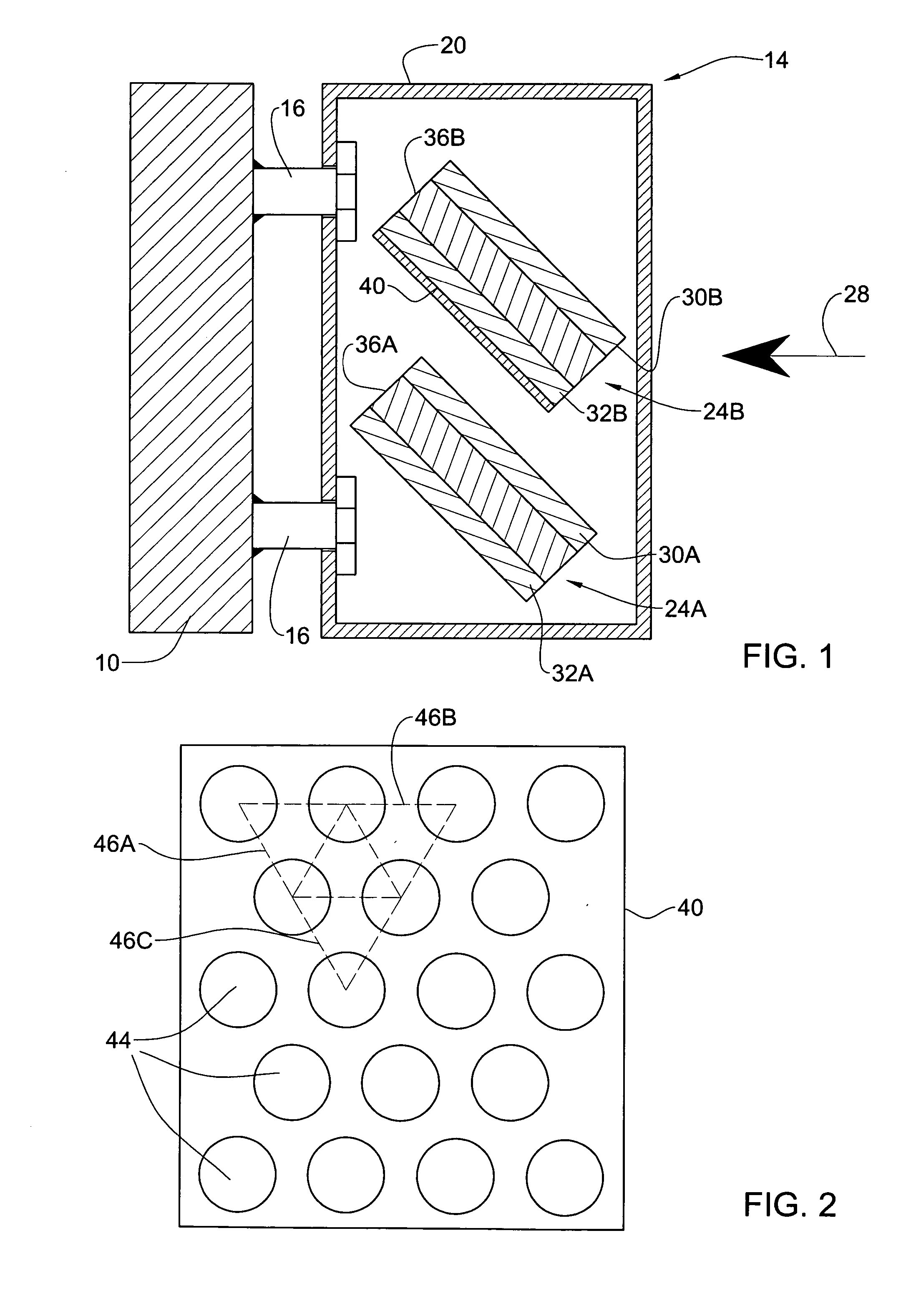
[0033] Turning first to FIG. 1, there is illustrated an external wall 10 of an enclosure, e.g. a combat vehicle, a structure, etc. fitted with an armor module (tile) 14 mounted thereto by bolts 16. The module 14 comprises a casing 20 accommodating, as an example only, two reactive cassettes 24A and 24B extending in a slant with respect to an expected oncoming shaped charge warhead, or kinetic projectile, represented by arrow 28.

[0034] Each of the reactive cassettes 24A and 24B comprises a front plate 30A and 30B, respectively, and a rear plate 32A and 32B, respectively, made for example of metal, sandwiching between them a layer of explosive material 36A and 36B, respectively.

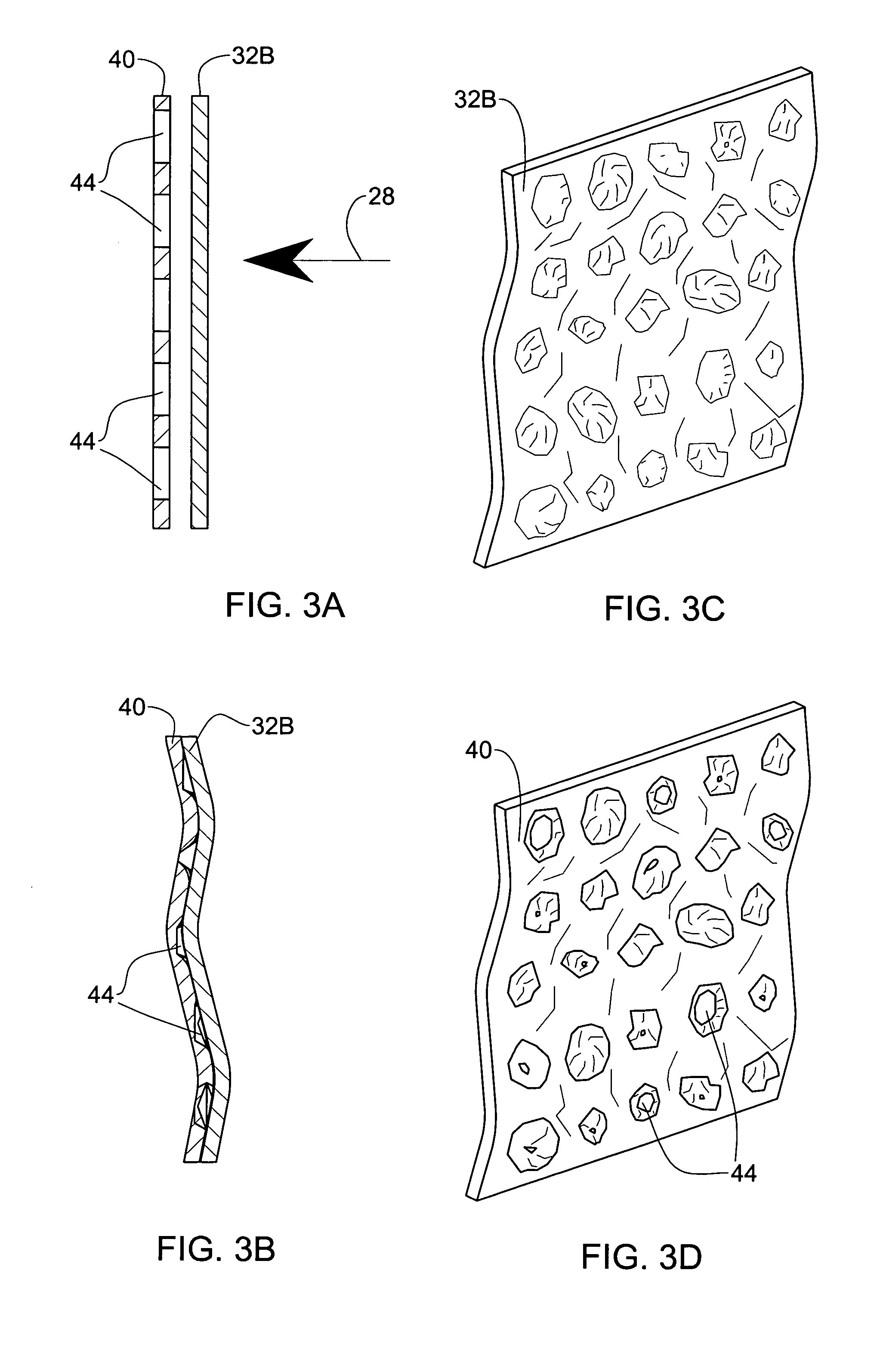
[0035] However, the cassette 24B differs from cassette 24A in that it further comprises, adjacent the rear metal plate 32B a dampening plate 40 which is shown in detail in FIG. 2.

[0036] Turning now to FIG. 2, it is seen that the dampening plate 40 is cavitated by a plurality of circular apertures 44 which in...


PUM


Abstract

A reactive armor cassette comprising at least a front plate and at least a back plate and sandwiching between them at least one layer of explosive material, and at least one dampening plate adjoining either or both said back plate and front plate and wherein the dampening plate is cavitated.

Description

FIELD OF THE INVENTION [0001] The present invention generally relates to energy absorbing / wasting systems useful for example in armor cassettes fitted for attaching on the outside of a structure or body liable to be exposed to attack by projectiles, e.g. shaped-charged warheads and kinetic energy projectiles. However, the system may be applied in other configuration comprising one or more moving plate members. [0002] Bodies and structures protectable by armor models in accordance with the present invention are, for example, vehicles such as battle tanks, armored personal carriers, armored fighting vehicles, armored self-propelled guns; helicopters, maritime vessels, static structures such as buildings, above-ground portions of bunkers, containers of various nature, for the storage of fuel, chemicals, ammunitions, etc. [0003] In particular, the present invention is concerned with an improvement for reactive armor cassettes for increasing kinetic energy absorbing on the one hand and, ...

Claims


Application Information

Patent Timeline
IPC IPC(8): B65D81/26
CPCF41H5/023F41H5/007
Inventor HANINA, EREZBENYAMI, MOSHEFRILING, SAMUEL
Owner THE STATE OF ISRAEL MINIST OF AGRI & RURAL DEV AGRI RES ORG ARO VOLCANI CENT
Learn More