Method of selectively decoupling solidborne noise, a laminated ball joint, a mechanical connection, and an aircraft

a solid-borne noise and selective decoupling technology, applied in the field of selective decoupling of solid-borne noise, can solve the problems of large noise in such aircraft, and achieve the effect of reducing the noise of aircraft and improving the comfort of the occupants of the aircra

Active Publication Date: 2007-02-15
EUROCOPTER
View PDF8 Cites 11 Cited by
  • Summary
  • Abstract
  • Description
  • Claims
  • Application Information

AI Technical Summary

Benefits of technology

[0010] Thus, a first object of the invention is to improve the comfort of the occupants of an aircraft such as a helicopter. Secondly, it seeks overall to reduce the noise from the aircraft, whether it is perceived inside the aircraft or outside it.
[0022] Consequently, it is appropriate to oppose transmission of such vibration from the main gearbox to the force transmission structure as much as possible in order to avoid premature wear of the elements that are subjected to said vibration or acceleration, and to make the cockpit and the passenger cabin of the aircraft comfortable.
[0066] Resonator means associated with respective bearing parts, either at their bottom ends (FR 2 499 505) or at their top ends (FR 2 669 982) serve essentially to reduce the transmission of rotor vibration by said bearing parts.
[0067] French patent document 2 787 161 describes an anti-vibration device for reducing the vibration transferred by a gearbox suspension of a rotary wing aircraft. An elastic annular element and resonator means are interposed in the middle of the bar. The vibration produces alternating rotary motion and the resonator means generates an anti-vibratory inertial force opposing said vibration and reducing the amount of vibration that is transferred.
[0073] U.S. Pat. No. 4,781,363 describes an anti-vibration device having primary and secondary fluid chambers for mounting between the main transmission gearbox and the fuselage of a helicopter in order to reduce the transmission of vibration between them.

Problems solved by technology

In any event, a large portion of the noise in such aircraft comes initially from such gearboxes.

Method used


Image

  • Method of selectively decoupling solidborne noise, a laminated ball joint, a mechanical connection, and an aircraft
  • Method of selectively decoupling solidborne noise, a laminated ball joint, a mechanical connection, and an aircraft
  • Method of selectively decoupling solidborne noise, a laminated ball joint, a mechanical connection, and an aircraft

Examples


Embodiment Construction

[0129] There follows a description of embodiments of the invention.

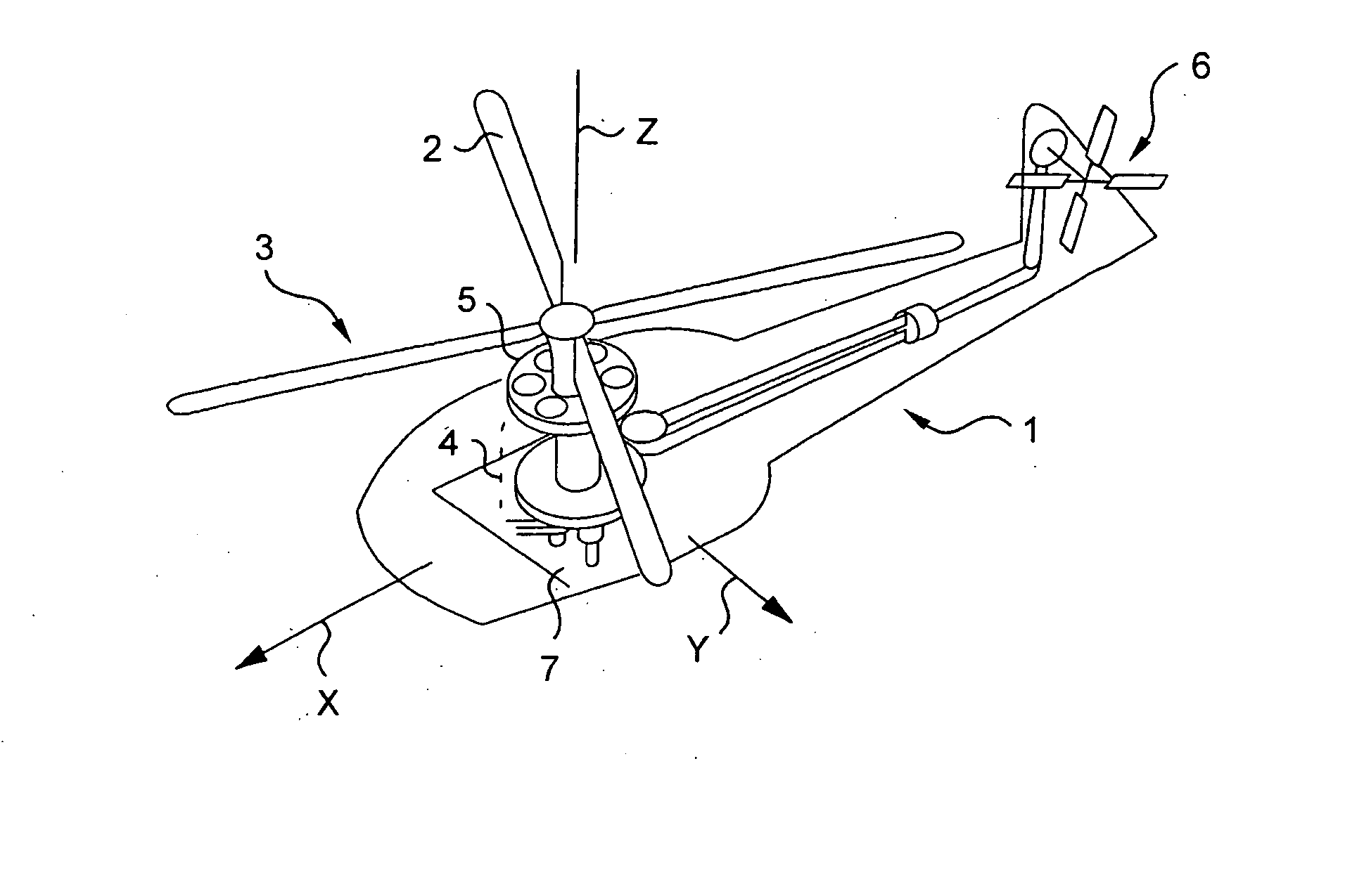
[0130] In the drawings, where similar elements are designated by the same reference numerals, there are also shown three mutual orthogonal directions.

[0131] An “elevation” direction Z corresponds to the height and the thickness of structures in the position in which they are described: terms such as up / down or bottom / top are relative thereto. For simplification purposes, this elevation direction Z is sometimes said to be vertical.

[0132] Another direction X is said to be axial, and corresponds to the long or main dimensions of the structures in the position in which they are described. Terms such as front / rear are relative thereto. For simplification purposes, this axial direction X is sometimes said to be horizontal.

[0133] Yet another direction Y is said to be “transverse”, and corresponds to the width or lateral direction of the structures in the position in which they are described. The term “side” is relative ...


PUM


Abstract

Solidborne noise and vibration is decoupled in a rotary wing aircraft by a laminated ball joint (15) for a suspension bar (13) of a transmission gearbox, the ball joint including at least two damper layers (19) dedicated to a frequency band for decoupling in the range 0 to 7000 Hz. For this purpose, the damper layers (19) and possibly also likewise dedicated interleaved layers (20) are given shape and / or dimension and / or physical-property parameters as a function of the frequency for decoupling in the determined frequency band.

Description

[0001] The invention relates in general to selective decoupling of solidborne noise and vibration as applied to a rotary wing aircraft. BACKGROUND OF THE INVENTION [0002] There follows an explanation of what is meant by the term “selective decoupling of solidborne noise”. [0003] Firstly concerning the concept of noise, it will be understood that the invention applies to the field of physical vibration and more particularly the range of audible sound. [0004] Nevertheless, the term “noise” should be understood herein broadly, i.e. sometimes going beyond the spectrum of frequencies that can be perceived by the human ear, in other words the audible spectrum. In this respect mention is sometimes made of “high” frequencies. [0005] Nevertheless, other ranges of vibration are sometimes also handled by the invention, on both sides of the audible spectrum. For example, the invention relates not only to ultrasound frequencies that can sometimes be troublesome (in particular for certain animals...

Claims


Application Information

Patent Timeline
IPC IPC(8): B64C27/00
CPCB64C2027/002B64C27/001
Inventor FERRER, ROGELIO
Owner EUROCOPTER
Why Eureka
Try Eureka