Detection of transmembrane potentials by optical methods

a transmembrane potential and optical method technology, applied in the direction of group 3/13 element organic compounds, peptides, group 5/15 element organic compounds, etc., can solve the problems of indicators that fail to give any shift in fluorescence wavelengths or ratiometric output, slow response of indicators,

Inactive Publication Date: 2007-02-01
RGT UNIV OF CALIFORNIA
View PDF11 Cites 6 Cited by
  • Summary
  • Abstract
  • Description
  • Claims
  • Application Information

AI Technical Summary

Benefits of technology

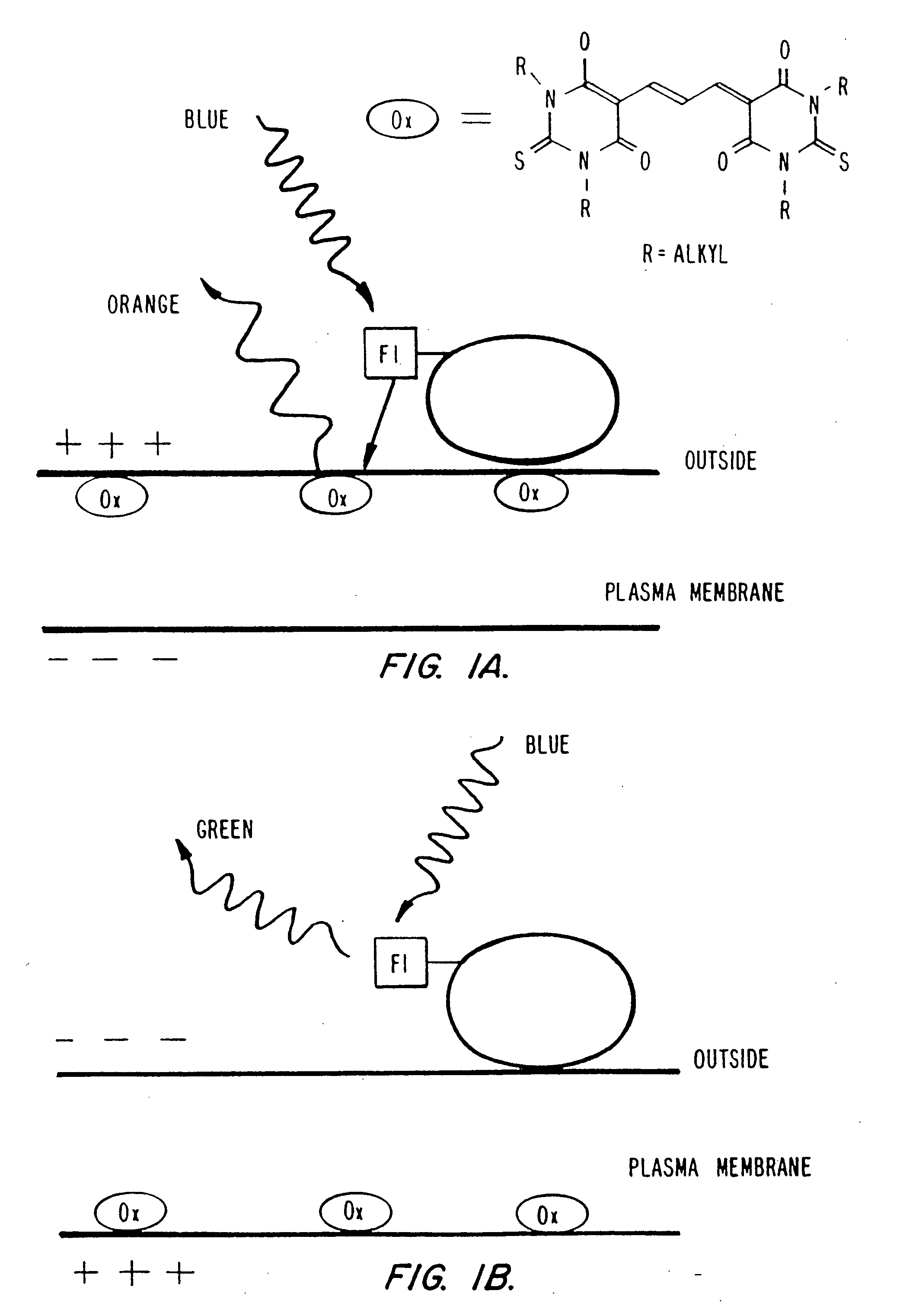
[0017] Preferably, the hydrophobic ion is an anion which labels the extracellular face of the plasma membrane. Upon addition of the hydrophobic fluorescent anion to the membrane, cell, or tissue preparation, the anion partitions into the plasma membrane, where it distributes between the extracellular and intracellular surfaces according to a Nernstian equilibrium. Changes in the membrane potential cause the fluorescent anion to migrate across the membrane so that it can continue to bind to whichever face (the intracellular or extracellular face) is now positively charged. Since the efficiency of energy transfer between the two reagents is a function of the distance between them and this distance varies as the fluorescent anion redistributes back and forth across the membrane, measurement of energy transfer provides a sensitive measure of changes in the transmembrane potential. For example, if the membrane potential (intracellular relative to extracellular) changes from negative to positive, the fluorescent hydrophobic anion is pulled from the extracellular surface to the intracellular surface of the plasma membrane. If the second reagent is one which is on the extracellular face, this results in an increase in the distance between the anion and the second reagent and a concomitant decrease in the efficiency of FRET and quenching between the two species. Thus, fluorescence measurements at appropriate excitation and emission wavelengths provide a fluorescent readout which is sensitive to the changes in the transmembrane potential. Typically, the time constant for the redistribution of the fluorescent anion is rapid and in the millisecond time scale thus allowing the convenient measurement both of rapid cellular electrical phenomena such as action potentials or ligand-evoked channel opening, as well as slower and more sustained changes evoked by altering the activity of ion pumps or exchangers.

Problems solved by technology

However, their responses are slow because to establish new equilibria, ions must diffuse through unstirred layers in each aqueous phase and the low-dielectric-constant interior of the plasma membrane.
Therefore, selectivity between cell types is difficult.
Also, any additions of hydrophobic proteins or reagents to the external solution, or changes in exposure to hydrophobic surfaces, are prone to cause artifacts.
These indicators also fail to give any shift in fluorescence wavelengths or ratiometric output.
However, they are insensitive because they sense the electric field with only a part of a unit charge moving less than the length of the molecule, which in turn is only a small fraction of the distance across the membrane.
Furthermore, a significant fraction of the total dye signal comes from molecules that sit on irrelevant membranes or cells and that dilute the signal from the few correctly placed molecules.

Method used


Image

  • Detection of transmembrane potentials by optical methods
  • Detection of transmembrane potentials by optical methods
  • Detection of transmembrane potentials by optical methods

Examples


example i

Synthesis of Oxonol Dyes

[0237] All starting materials and reagents were of the highest purity available (Aldrich; Milwaukee, Wis.) and used without further purification, except where noted. Solvents were HPLC grade (Fisher) and were dried over activated molecular sieves 3 Å. NMR spectra were acquired on a Varian Gemini 200 MHz spectrometer (Palo Alto, Calif.). The spectra were referenced relative to the residual solvent peak (CHCl3, =7.24 ppm). Fluorescence spectra were taken on a SPEX Fluorolog-2 (Edison, N.J.) and were corrected for lamp and detector wavelength variations using the manufacturer supplied correction files.

Bis-(1,3-dibutyl-2-thiobarbiturate)-trimethineoxonol DiSBA-C4-(3)

[0238] DiSBA-C4-(3) was synthesized based on the procedure for the ethyl derivative [British Patent 1,231,884]. 1,3-di-butyl-thiobarbiturate (500 mg, 2 mmol) was dissolved in 700 μL of pyridine. To this solution, a mixture of 181 μL (1.1 mmol) of malonaldehyde bis(dimethyl acetal) and 100 μL of 1 M...

example ii

Synthesis of Fluorescent Phospholipids

[0242] Cou-PE:3-amidoglycine-6-chloro-7-butyryloxy coumarin was synthesized as described in pending U.S. patent application Ser. No. 08 / 407,554, filed Mar. 20, 1995 as set out below. For synthesis of 2,4 dihydroxy-5-chlorobenzaldehyde, 21.7 g (0.15 Mol) 4-chlororesorcinol were dissolved in 150 ml dry diethyl ether and 27 g finely powdered zinc (II) cyanide and 0.5 g potassium chloride were added with stirring. The suspension was cooled on ice. A strong stream of hydrogen chloride gas was blown into the solution with vigorous stirring. After approximately 30 minutes the reactants were dissolved. The addition of hydrogen chloride gas was continued until it stopped being absorbed in the ether solution (approx. 1 hour). During this time a precipitate formed. The suspension was stirred for one additional hour on ice. Then the solid was let to settle. The ethereal solution was poured from the solid. The solid was treated with 100 g of ice and heated ...

example iii

Synthesis of Linker for Donors and Acceptors

[0249] This example is with reference to FIGS. 14-16. 12-p-methoxybenzylthio-1-dodecanol (1): Na (800 mg, 34.8 mmol) was dissolved in 30 mL of dry MeOH. Under argon, p-methoxybenzylmercaptan (2.75 mL, 3.04 g, 19.7 mmol) was added to the methoxide solution. After a few minutes, 12-bromododecanol (2.5 g, 9.43 mmol) was dropped into the reaction mixture. Within 5 minutes a solid began to come out of solution. After a minimum of 3 h, the reaction was filtered and washed 3× with cold MeOH, yielding 2.874 g (8.49 mmol, 90%) of pure product after drying. 1H NMR (CDCl3): d 7.23 (d, J=8.8 Hz, 2H, AA′ of AA′ BB′ aromatic system), 6.85 (d, J=8.8 Hz, 2H, BB′ of AA′ BB′ aromatic system), 3.80 (s, 3H, methoxy), 3.66 (s, 2H, benzyl), 3.64 (dt, J1=6.6 Hz, J2=5.5 Hz, 2H, RCH2OH), 2.40 (t, J-7.3 Hz, 2H, RSCH2R), 1.50-1.65 (cm, 4H, CH2 b to heteroatoms), 1.2-1.4 (cm, 16H, bulk methylenes).

[0250] 12-p-methoxybenzylthio-1-bromododecane (2): (1) (500 mg, 1.48...


PUM

PropertyMeasurementUnit
timeaaaaaaaaaa
timeaaaaaaaaaa
timeaaaaaaaaaa

Abstract

Methods and compositions are provided for determining the potential of a membrane. In one aspect, the method comprises: (a) introducing a first reagent comprising a hydrophobic fluorescent ion capable of redistributing from a first face of the membrane to a second face of the membrane in response to changes in the potential of the membrane, as described by the Nernst equation, (b) introducing a second reagent which labels the first face or the second face of the membrane, which second reagent comprises a chromophore capable of undergoing energy transfer by either (i) donating excited state energy to the fluorescent ion, or (ii) accepting excited state energy from the fluorescent ion, (c) exposing the membrane to radiation; (d) measuring energy transfer between the fluorescent ion and the second reagent, and (e) relating the energy transfer to the membrane potential. Energy transfer is typically measured by fluorescence resonance energy transfer. In some embodiments the first and second reagents are bound together by a suitable linker. In one aspect the method is used to identify compounds which modulate membrane potentials in biological membranes.

Description

[0001] This invention was made with Government support under Grant No. R01 NS27177-07, awarded by the National Institutes of Health. The Government has certain rights in this invention.BACKGROUND OF THE INVENTION [0002] The present invention relates generally to the detection and measurement of transmembrane potentials. In particular, the present invention is directed to compositions and optical methods for determining transmembrane potentials across the plasma membrane of biological cells. [0003] Fluorescence detection and imaging of cellular electrical activity is a technique of great importance and potential (Grinvald, A., Frostig, R. D., Lieke, E., and Hildesheim, R. 1988. Optical imaging of neuronal activity. Physiol. Rev. 68:1285-1366; Salzberg, B. M. 1983. Optical recording of electrical activity in neurons using molecular probes. In Current Methods in Cellular Neurobiology. J. L. Barker, editor. Wiley, New York. 139-187; Cohen, L. B. and S. Lesher. 1985. Optical monitoring o...

Claims


Application Information

Patent Timeline
Patent Type & Authority Applications(United States)
IPC IPC(8): C12Q1/00G01N33/53C07K14/47C07K16/46C07D403/02C07D209/08G01N21/78C07D213/74C07D215/22C07D215/48C07D215/50C07D215/54C07D239/60C07D239/62C07D239/66C07D311/08C07D311/16C07D335/06C07F5/00C07F5/02C07F9/10C07F9/572C09B23/02C09K11/06G01N21/76G01N33/50G01N33/52G01N33/542G01N33/58G01N33/68
CPCC07D209/08G01N2500/10C07D239/62C07D239/66C07D311/16C07F5/003C07F5/02C07F5/027C07F9/10C07F9/5728C09B23/02G01N33/5005G01N33/5008G01N33/502G01N33/5044G01N33/5058G01N33/5076G01N33/52G01N33/542G01N33/582G01N33/6872C07D239/60G01N33/5061Y10S436/80Y10S436/805
Inventor TSIEN, ROGER Y.GONZALEZ, JESUS E. III
Owner RGT UNIV OF CALIFORNIA
Why Eureka
Try Eureka