
Door bolt position detection system with light switching capability and a backup timer

a technology of position detection system and backup timer, which is applied in the direction of non-mechanical control, electric lighting source, alarm lock, etc., can solve the problems of not having enough lighting near the entrance of the storage room for a tenant, affecting the contact of the reed switch, and affecting the usability of the tenant's storage room,

Inactive Publication Date: 2007-02-01
JOLLEY DANIEL M +1
View PDF13 Cites 27 Cited by
  • Summary
  • Abstract
  • Description
  • Claims
  • Application Information

AI Technical Summary

Benefits of technology

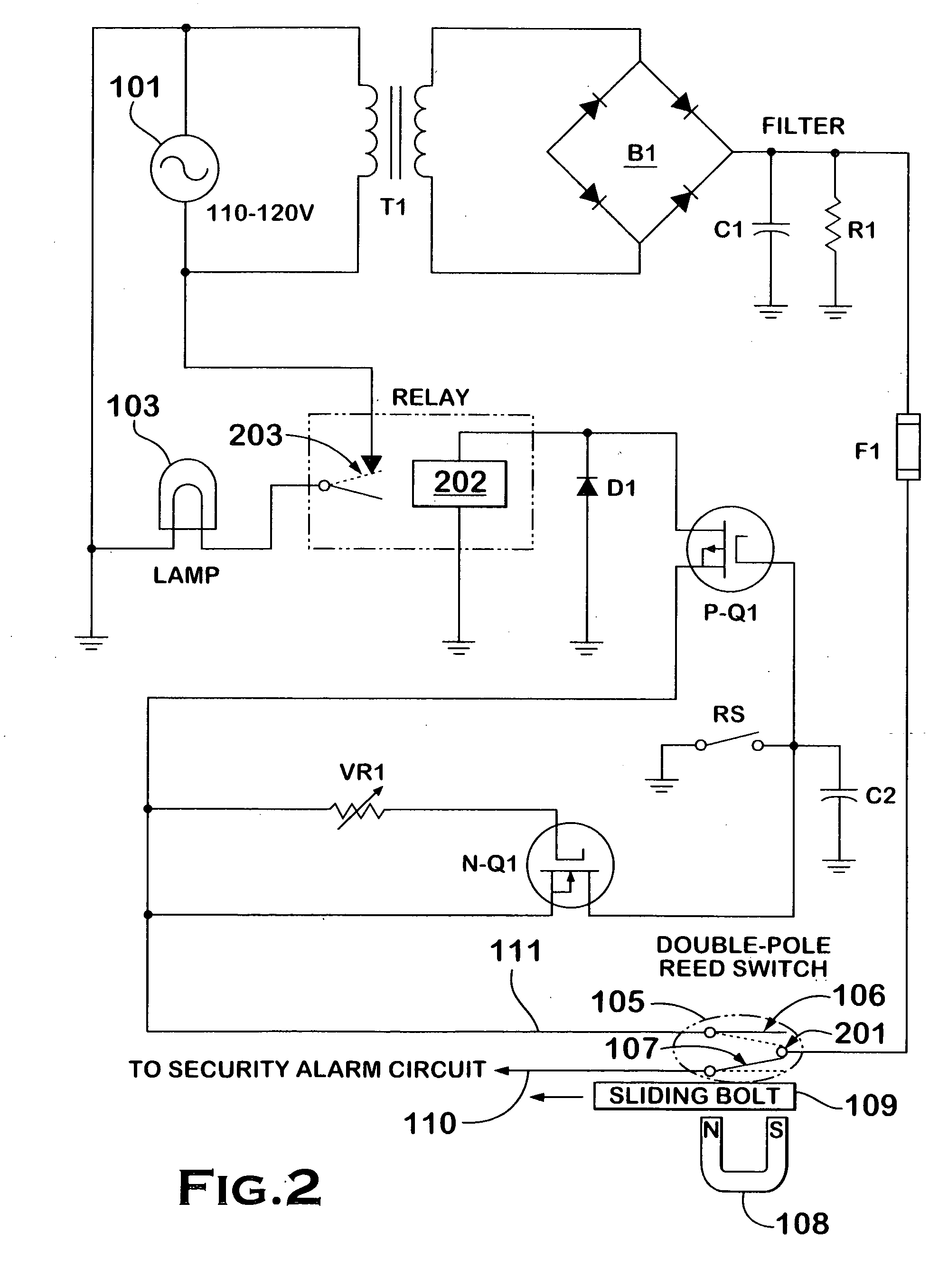
[0008] When the reed switch that controls the storage unit lighting is closed by withdrawal of the bolt from the track aperture, a low voltage power signal is sent through a normally-on switch to the coil of the relay, thereby closing the relay contacts and turning on the storage unit lights. The normally-on switch is a p-channel insulated gate field effect transistor (IGFET). At the same time the low voltage is sent through the no

Problems solved by technology

As a ferromagnetic bolt is employed to look the door, the bolt interferes with the magnetic field, thus affecting the reed switch's contacts.
In addition, the storage room may be located inside a storage facility structure, but may not have enough lighting near the entrance of the storage room to be usable by a tenant.
However, the provision of interior lighting for individual storage rooms is problematic; the tenant may fail to turn off the lights when he or she leaves the storage facility.
However, this method of controlling the internal lighting suffers from the drawback that when the individual storage room is if left unlocked—either inadvertently or during periods when it is not rented the lights will remain on.
Another problem with a bolt related switch is that the switch may fail in the on position with the lights remaining permanently on.
For these reasons, owners of many storage facilities have been reluctant to provide interior lighting for individual storage rooms because it may significantly drive up their utility expenditures.

Method used


Image

  • Door bolt position detection system with light switching capability and a backup timer
  • Door bolt position detection system with light switching capability and a backup timer
  • Door bolt position detection system with light switching capability and a backup timer

Examples


Embodiment Construction

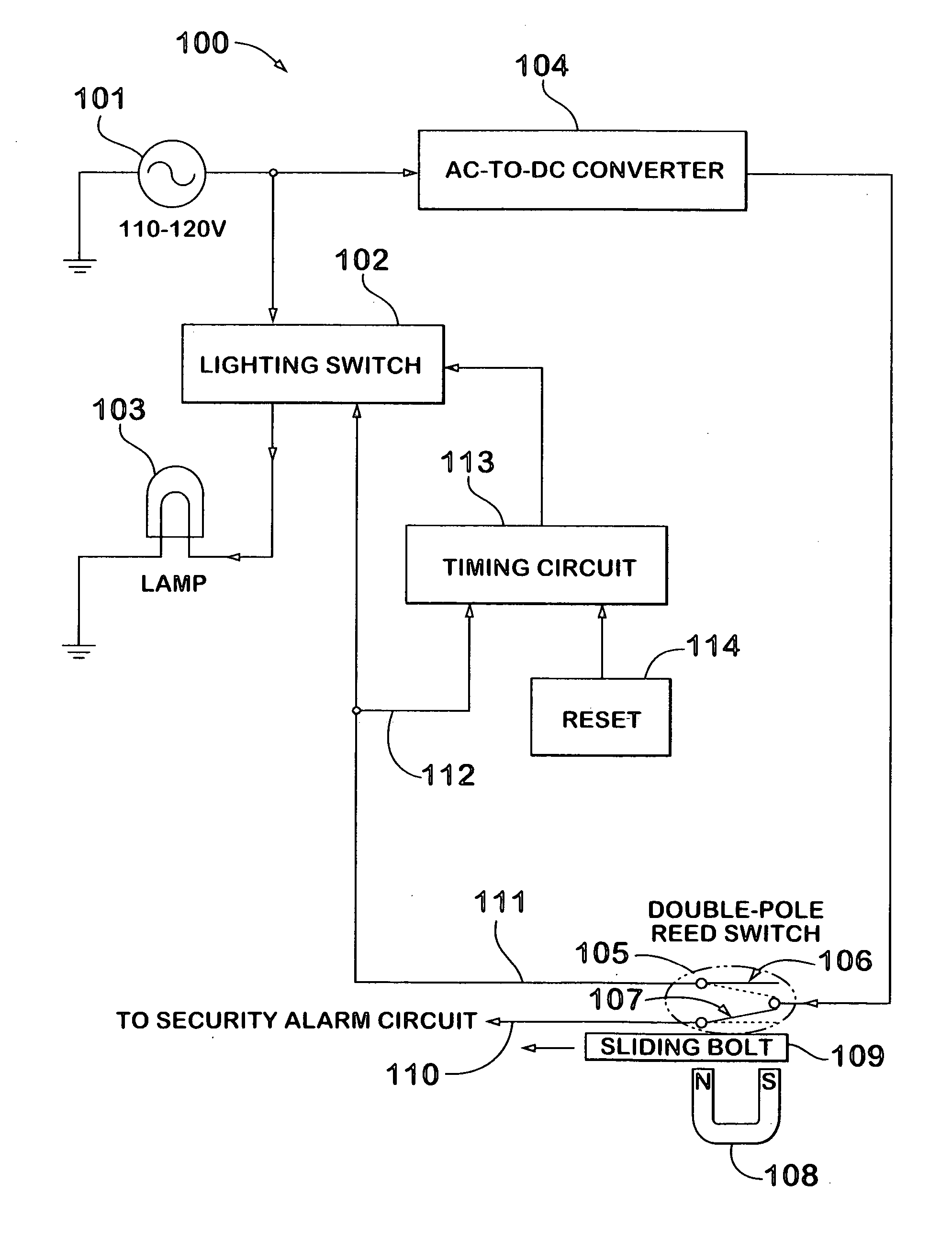
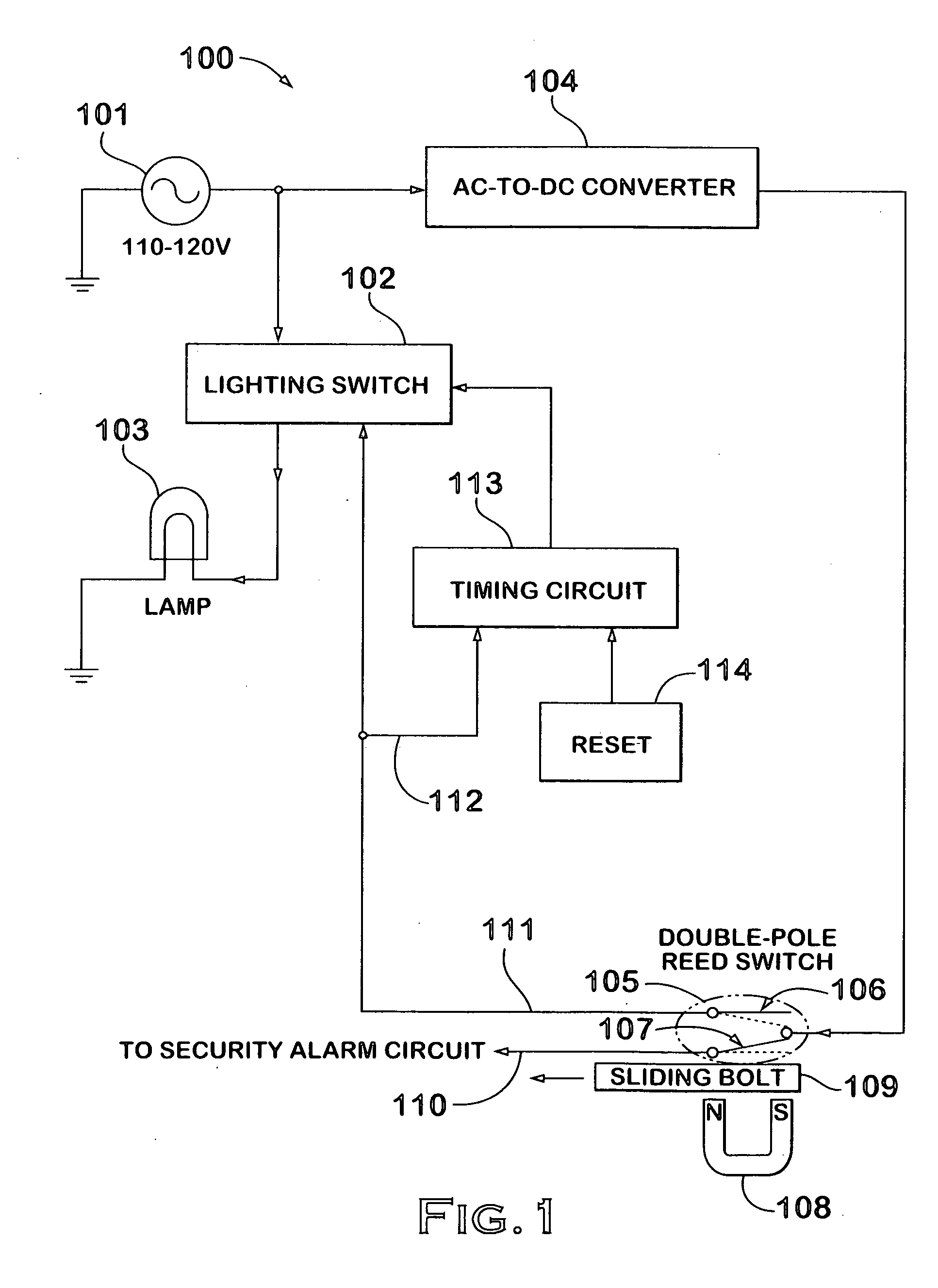
[0015] The invention will now be described with reference to the attached drawing figures. Referring to the block diagram of FIG. 1, a generalized circuit 100 for implementing the invention is shown. 100-120 volt alternating line current 101 is fed to both a lighting switch 102 and to an AC-to-DC converter 104. DC output from converter 104 is fed to a double-pole reed switch 105. For this particular embodiment of the invention, a portion of the reed switch 105 is utilized to control a lighting circuit is normally open and the same reed switch used for a security alarm signal generation, which is in the normally closed section. A sliding bolt 107 is fabricated from a ferromagnetic material, such as iron or steel. When placed between the permanent magnet 106 and the reed switch 105, the bolt 107 interferes with the propagation of the magnetic field of the magnet 108, and the reeds assume their normal positions. However, when the bolt 107 is withdrawn from between the magnet 106 and th...


PUM


Abstract

A door latch position detection system incorporating light switching capability and a backup timer includes a relay that is used to switch on the storage unit lighting powered by line voltage. The system includes an AC to DC converter that converts and filters the line voltage to low voltage DC power. The low voltage is fed to a reed switch within a switch housing attached to the overhead door track. When the reed switch that controls the storage unit lighting is closed by withdrawal of the bolt from the track aperture, a low voltage power signal is sent through a normally-on switch to the coil of the relay, thereby closing the relay contacts and turning on the storage unit lights. A timer shuts off the current to the relay after a set period. The present invention may also be utilized in a garage or closet to conserve energy.

Description

CROSS REFERENCE TO RELATED APPLICATIONS [0001] This application is related to U.S. provisional application Ser. No. 09 / 659,862, now U.S. Pat. No. 6,359,538 dated Mar. 19, 2002, by the same inventors, which is incorporated by reference as if fully set forth.BACKGROUND OF THE INVENTION [0002] This invention relates to door position detection systems employing magnetic reed switches. A reed switch is a mechanical electrical switch having a pair of ferromagnetic contacts in either a normally-open or normally-closed configuration. In the presence of a magnetic field, the contacts of a normally-open reed switch will close, conversely the contacts of a normally-closed read switch will open. Reed switches are typically used as proximity sensors for limit, safety, and security applications. [0003] Overhead security doors are generally mounted between two parallel tracks. For buildings having a height at least double the door height, the tracks may be entirely vertical. However, for buildings...

Claims


Application Information

Patent Timeline
IPC IPC(8): E05B45/06
CPCE05B17/10E05B65/0021E05B2047/0068Y02B20/42H05B37/0209H05B37/0281E05B2047/0069H05B47/10H05B47/16Y02B20/40
Inventor JOLLEY, DANIEL M.CARLSON, WILLIAM R.
Owner JOLLEY DANIEL M
Learn More