Aerodynamically efficient surface

a surface and aerodynamic technology, applied in the direction of drag reduction, air flow influencers, mechanical instruments, etc., can solve the problems of tubular cavities and inability to teach the use of waves with breaks, etc., and achieve the effect of shedding a fluid medium

Inactive Publication Date: 2007-01-25
SCHMIDT ERIC THOMAS
View PDF14 Cites 28 Cited by
  • Summary
  • Abstract
  • Description
  • Claims
  • Application Information

AI Technical Summary

Benefits of technology

[0007] The object of the present invention is to orchestrate and direct the flow between a solid surface and an adjacent fluid medium in relative motion. The present invention has further intention to shed a fluid medium from a solid surface more efficiently, through the use of tiles comprised of wave forms to be ap

Problems solved by technology

Elimination of drag in motion is one answer to efficiency U.S. Pat. No. 5,114,099 (Gao et al.) shows a series of wavelets in a diamond pattern with a ridge lengthwise and convex sloping sides from the ridge, however does not teach the use of waves with breaks or tubular cavities.
Nor does Gao teach the use of a wave panel the shape of a drip.

Method used


Image

  • Aerodynamically efficient surface
  • Aerodynamically efficient surface
  • Aerodynamically efficient surface

Examples


Embodiment Construction

[0020] Disclosed is one embodiment for the present invention. It will be clear to one skilled in the art that numerous other embodiments and / or uses for the disclosed technologies are possible which would fall within the scope and spirit of those embodiments specified herein.

[0021] The design of the present invention has many aerodynamic advantages over the prior art surfaces. Especially when used on the exterior surface of a vehicle.

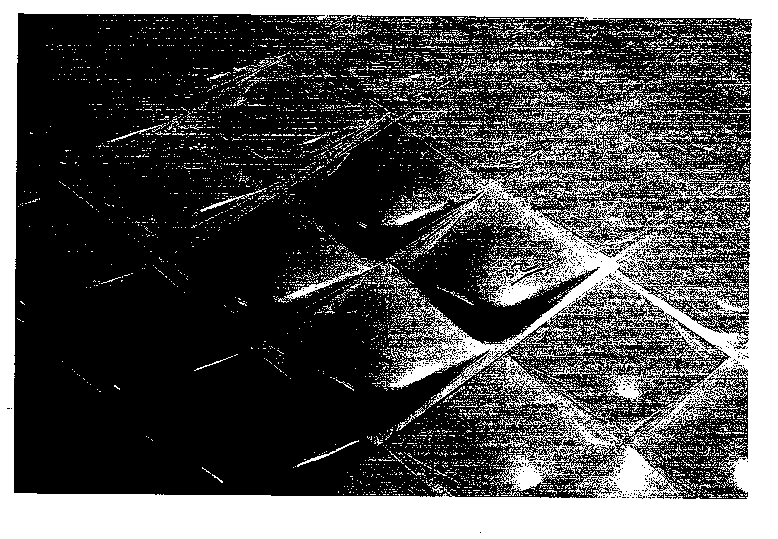
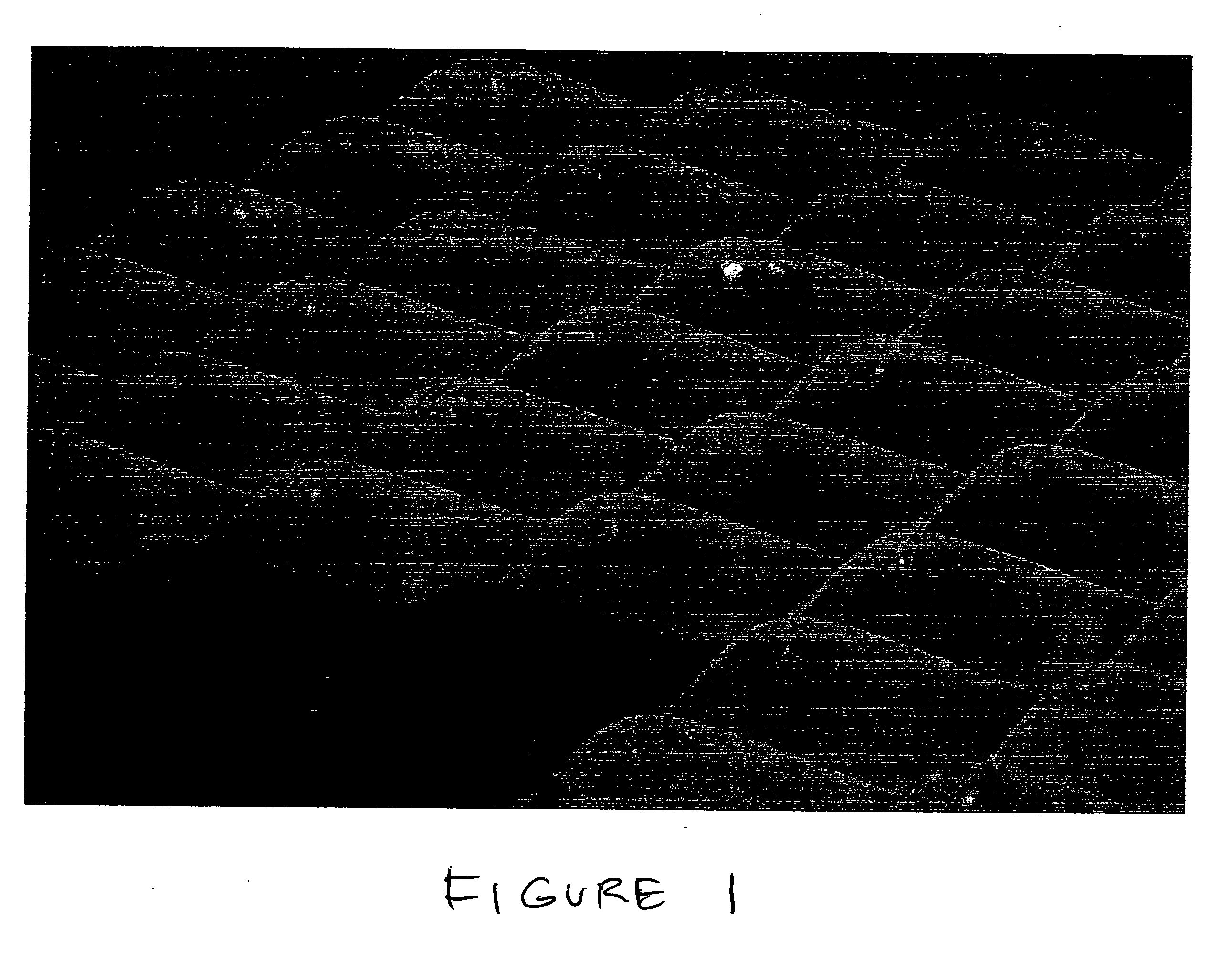
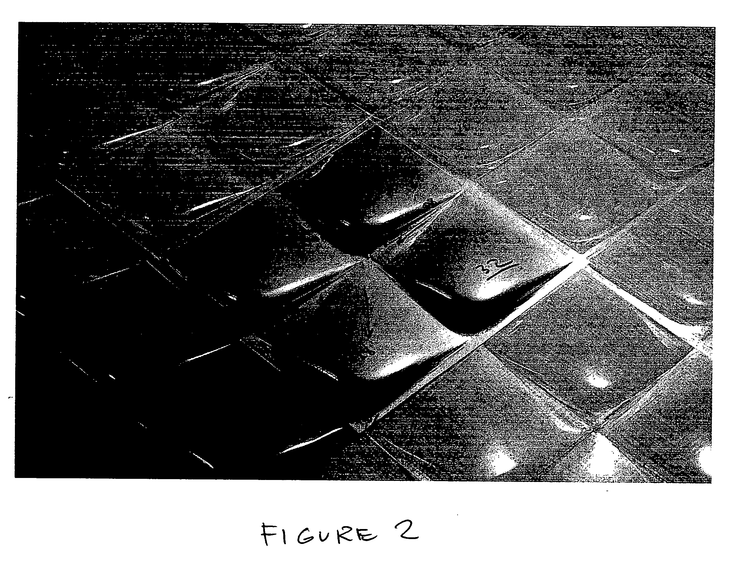
[0022] The specifics may best be understood by referencing the attached photographs of one possible variation of a wave form tile.

[0023]FIG. 1 is a perspective view of (photograph) multiple sheets of the devices of the present invention. As you can see the independent sheets are arranged to create an irregular surface of organized waves which are usable on a vehicle or other device that travels through the air (or water), as well as devices used for management of a fluid, such as an air duct.

[0024]FIG. 2 shows a multi-wave tile 10. The individual ti...


PUM


Abstract

A Tile, in the form of a natural wave, is provided to replace traditionally smooth surfaces to aid in more efficient shedding of a fluid medium.

Description

Claims benefit of Provisional App. #60 / 698,454 filed Jul. 11, 2005STATEMENT REGARDING FEDERALLY SPONSORED RESEARCH OR DEVELOPMENT [0001] None. BACKGROUND OF THE INVENTION [0002] 1. Field of the Invention [0003] The present invention relates generally to the field of fluid dynamic drag reduction. More specifically, the present invention pertains to techniques or devices for regulating the flow of air or water passing over a surface to reduce exposure or drag. [0004] 2. Description of the Related Art [0005] The invention of the wheel started a movement to seek efficiency through less friction. Elimination of drag in motion is one answer to efficiency U.S. Pat. No. 5,114,099 (Gao et al.) shows a series of wavelets in a diamond pattern with a ridge lengthwise and convex sloping sides from the ridge, however does not teach the use of waves with breaks or tubular cavities. Nor does Gao teach the use of a wave panel the shape of a drip. [0006] U.S. Pat. No. 2,800,291 (Stephens et.al) claim...

Claims


Application Information

Patent Timeline
IPC IPC(8): B64C21/10
CPCB64C21/10B64C2230/26Y02T50/166F15D1/12Y02T50/10
Inventor SCHMIDT, ERIC THOMAS
Owner SCHMIDT ERIC THOMAS
Why Eureka
Try Eureka