
Method and apparatus for resistive characteristic assessment

Inactive Publication Date: 2007-01-18
BARNES JEWISH HOSPITAL
View PDF35 Cites 11 Cited by
  • Summary
  • Abstract
  • Description
  • Claims
  • Application Information

AI Technical Summary

Benefits of technology

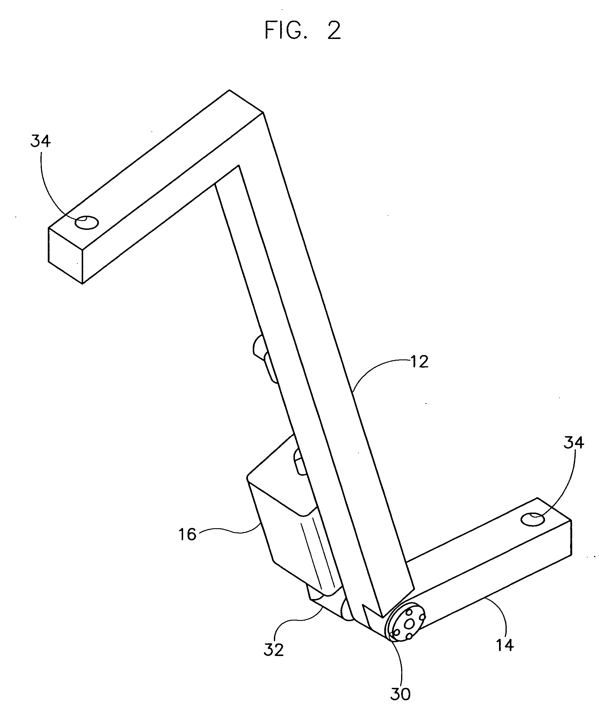
[0007] Briefly, the present invention includes a simulated limb for training an evaluator to assess a resistive characteristic such as spasticity or strength of an animal. The limb comprises a first member simulating a first portion of the animal and a second member simulating a second portion of the animal rotatably connected to the first member. The limb also has a resistance element operatively connected between the first member and the second member having a selectively variable resistance that varies an amount of torque required to rotate the second member of the simulated limb relative to the first member. In addition, the limb includes a processor operatively connected to the resistance element and adapted for adjusting the resistance of the resistance element over a range of rotation of the second member relative to the first member thereby providing a resistance profile for the simulated limb mimicking the resistive characteristic of the animal.

Problems solved by technology

Even with training, the repeatability and reliability of the test has been questioned.
Muscle weakness, or lack of strength, is also a common problem in cerebral palsy, stroke, spinal cord injury and other disabilities.
Weakness is related to the inability of the patient to actively produce or control torque about a joint.
A major reason for the lack of reliability in both the Modified Ashworth Scale and manual muscle tests is the different physical characteristics of the evaluators and the patients.
Evaluators of differing gender, size and strength may not sense patient resistant forces equally.
Although reliable and accurate methods exist for assessing spasticity and strength, the methods are complex and require special training and equipment.

Method used


Image

  • Method and apparatus for resistive characteristic assessment
  • Method and apparatus for resistive characteristic assessment
  • Method and apparatus for resistive characteristic assessment

Examples


Embodiment Construction

[0015] Referring now to the drawings and in particular to FIG. 1, a simulated limb system for training an evaluator to assess a resistive characteristic such as spasticity or strength of an animal such as a human is designated in its entirety by the reference numeral 10. The limb 10 generally comprises a first member (generally designated by 12) simulating a first portion of the animal (e.g., a calf of a human) and a second member (generally designated by 14) simulating a second portion of the animal (e.g., a foot of the human) rotatably connected to the first member. A resistance element 16 is operatively connected between the first member 12 and the second member 14. The element 16 has a selectively variable resistance that varies an amount of torque required to rotate the second member 14 of the simulated limb 10 relative to the first member 12. Although other resistance elements may be used without departing from the scope of the present invention, in one embodiment the resistan...


PUM


Abstract

A simulated limb for training an evaluator to assess a resistive characteristic of an animal. The limb includes a first member simulating a first portion of the animal, and a second member simulating a second portion of the animal rotatably connected to the first member. The limb also includes a resistance element having a variable resistance that varies an amount of torque required to rotate the second member relative to the first member. A method for training an evaluator to assess a resistive characteristic using a simulated limb includes adjusting the resistance of the resistance element over a range of rotation thereby providing a resistance profile for the simulated limb mimicking the resistive characteristic of the animal. A method for simulating a resistive characteristic of an animal using a simulated limb includes applying a resistance profile to the simulated limb mimicking spasticity or muscle strength over a range of rotation.

Description

[0001] This invention was made with government support under grants from the National Institutes of Health (R43 HD044269). The U.S. government has certain rights in this invention.BACKGROUND OF THE INVENTION [0002] The present invention relates generally to a method for training healthcare professionals, and more particularly to a method for training an evaluator to assess a resistive characteristic such as spasticity or strength of an animal, particularly a human. [0003] Spasticity is a major issue in cerebral palsy, stroke, spinal cord injury and other neurological disorders. The term spasticity is often used to refer to impairments including muscle hypertonia, hyperactive deep tendon reflex, clonus and velocity dependent resistance to passive stretch. Many surgical and therapeutic procedures are performed and pharmacological drugs used on persons having spasticity to minimize or eliminate impairment. Methods to quantify the various types of spasticity include the Modified Ashwort...

Claims


Application Information

Patent Timeline
IPC IPC(8): A61B5/22
CPCA61B5/224A61B5/4519G09B23/32G09B19/00G09B23/28A61B5/4528
Inventor ENGSBERG, JACK R.ENGSBERG, DAVID P.ROSS, SANDY A.
Owner BARNES JEWISH HOSPITAL
Learn More