
Objective-lens driving apparatus and optical disk apparatus

a driving apparatus and optical disk technology, applied in the direction of data recording, disposition/mounting of heads, instruments, etc., can solve the problems of imposing restrictions on the size of permanent magnets, focusing coils, tracking coils, and unable to correctly record information on the disk, so as to reduce the time

Inactive Publication Date: 2007-01-04
HITACHI MEDIA ELECTORONICS CO LTD
View PDF15 Cites 4 Cited by
  • Summary
  • Abstract
  • Description
  • Claims
  • Application Information

AI Technical Summary

Benefits of technology

[0007] It is an object of the present invention to provide an objective-lens driving apparatus and an optical disk apparatus where, even when the objective lens is displaced, the inclination of the objective lens become small, and the dependency on the size of magnetic circuit become low.
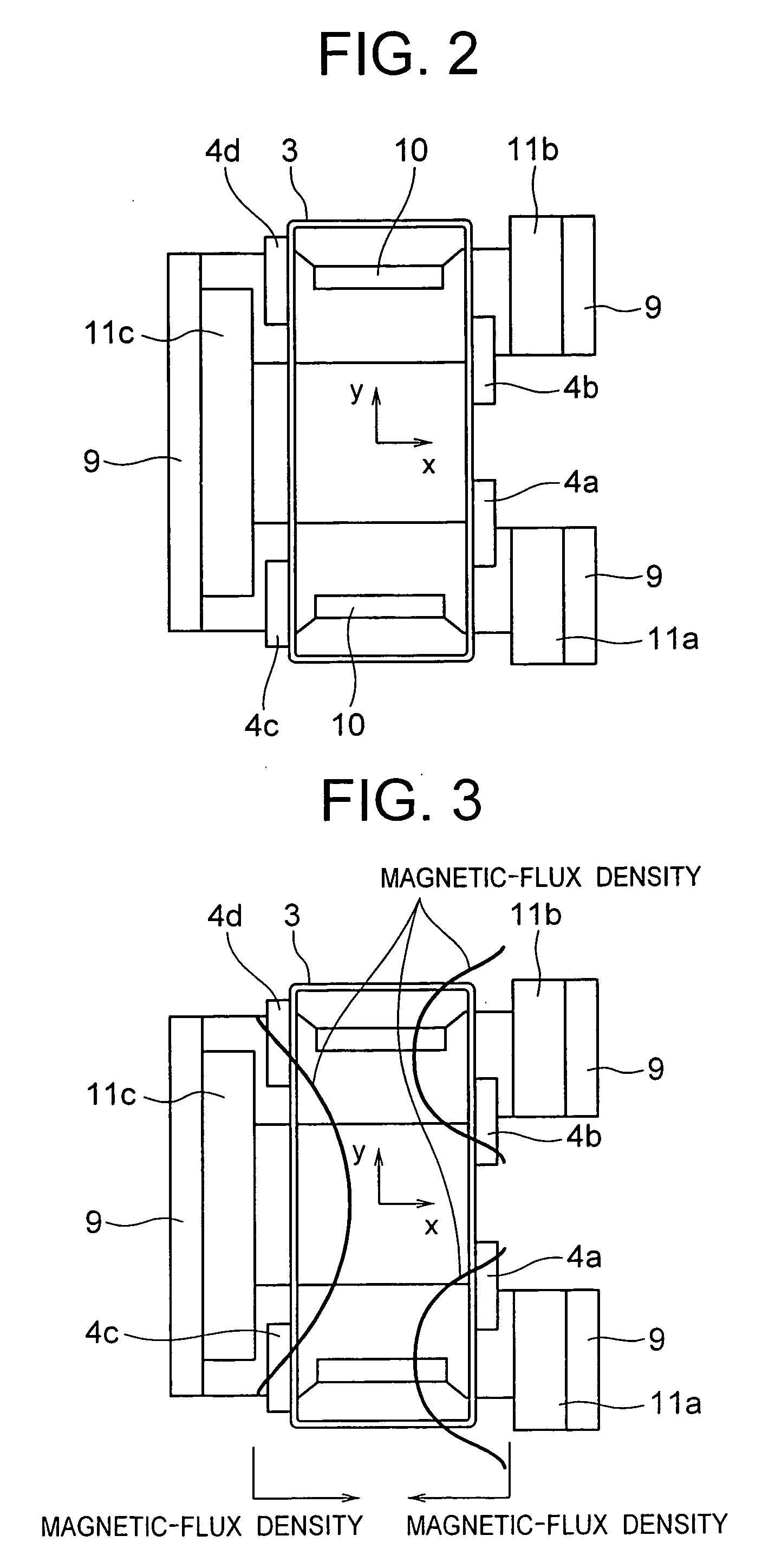
[0009] With the permanent magnets, the focusing coil and the tracking coil arranged as described above, this configuration makes it possible to reduce each moment generated at each of the focusing coil and the tracking coil when the objective lens is displaced. Accordingly, it becomes possible to implement the objective-lens driving apparatus and, eventually, the optical disk apparatus where the inclination of the objective lens becomes small.

Problems solved by technology

This makes it impossible to correctly record the information on the disk, or results in a degradation in the reproduced signal.
This setting, however, imposes the restrictions on the sizes of the permanent magnet, the focusing coil, and the tracking coil.
As a consequence, the design's degree-of-freedom has been limited, and there has been acquired only effect that is not necessarily sufficient in an aspect of the apparatus's downsizing.

Method used


Image

  • Objective-lens driving apparatus and optical disk apparatus
  • Objective-lens driving apparatus and optical disk apparatus
  • Objective-lens driving apparatus and optical disk apparatus

Examples


Embodiment Construction

[0020] Referring to the drawings, the explanation will be given below concerning embodiments of the present invention. The optical disk apparatus according to the present invention drives the objective lens by the objective-lens driving apparatus so as to light-converge light on the recording surface of the optical disk, thereby performing the reproduction of information.

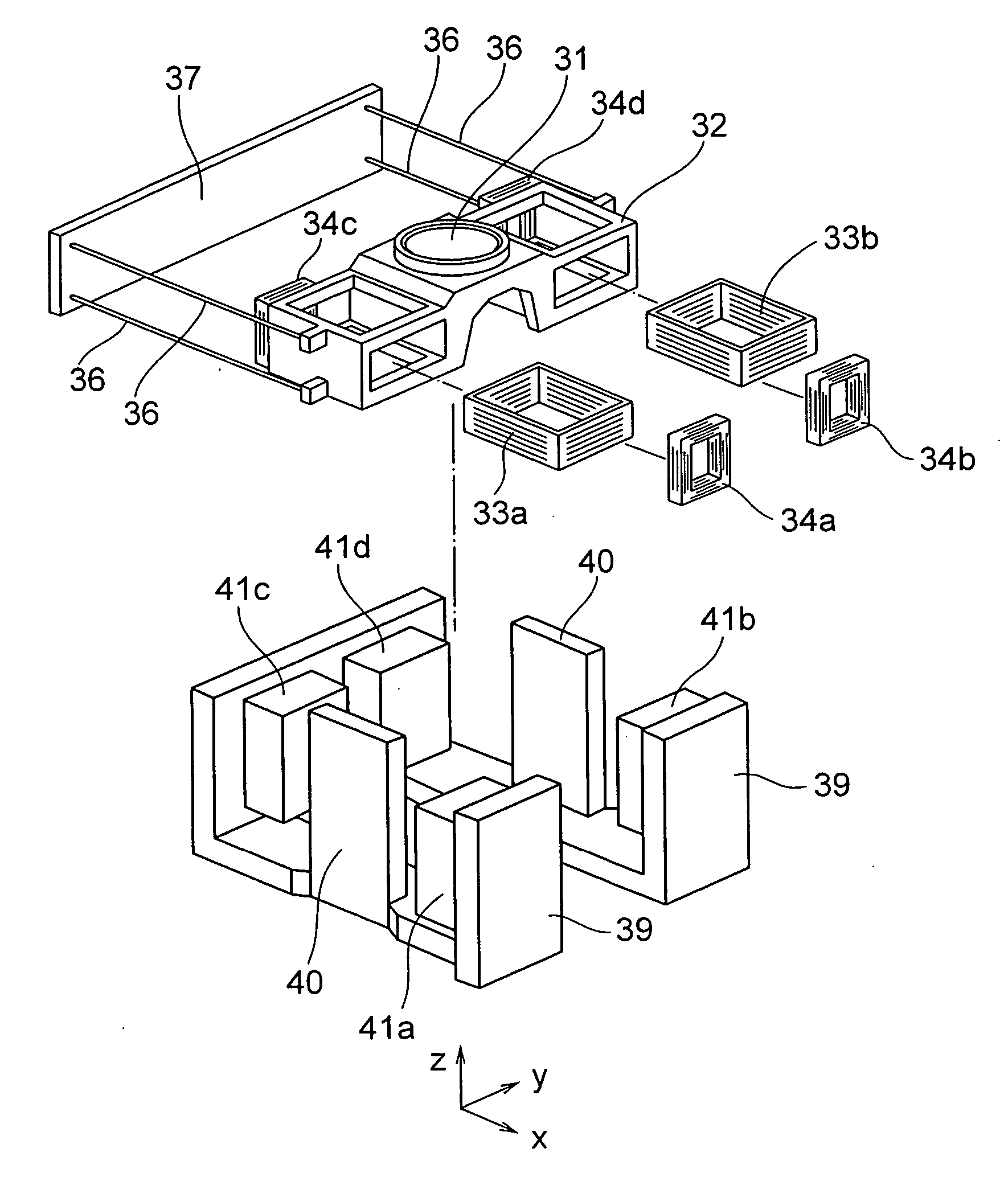
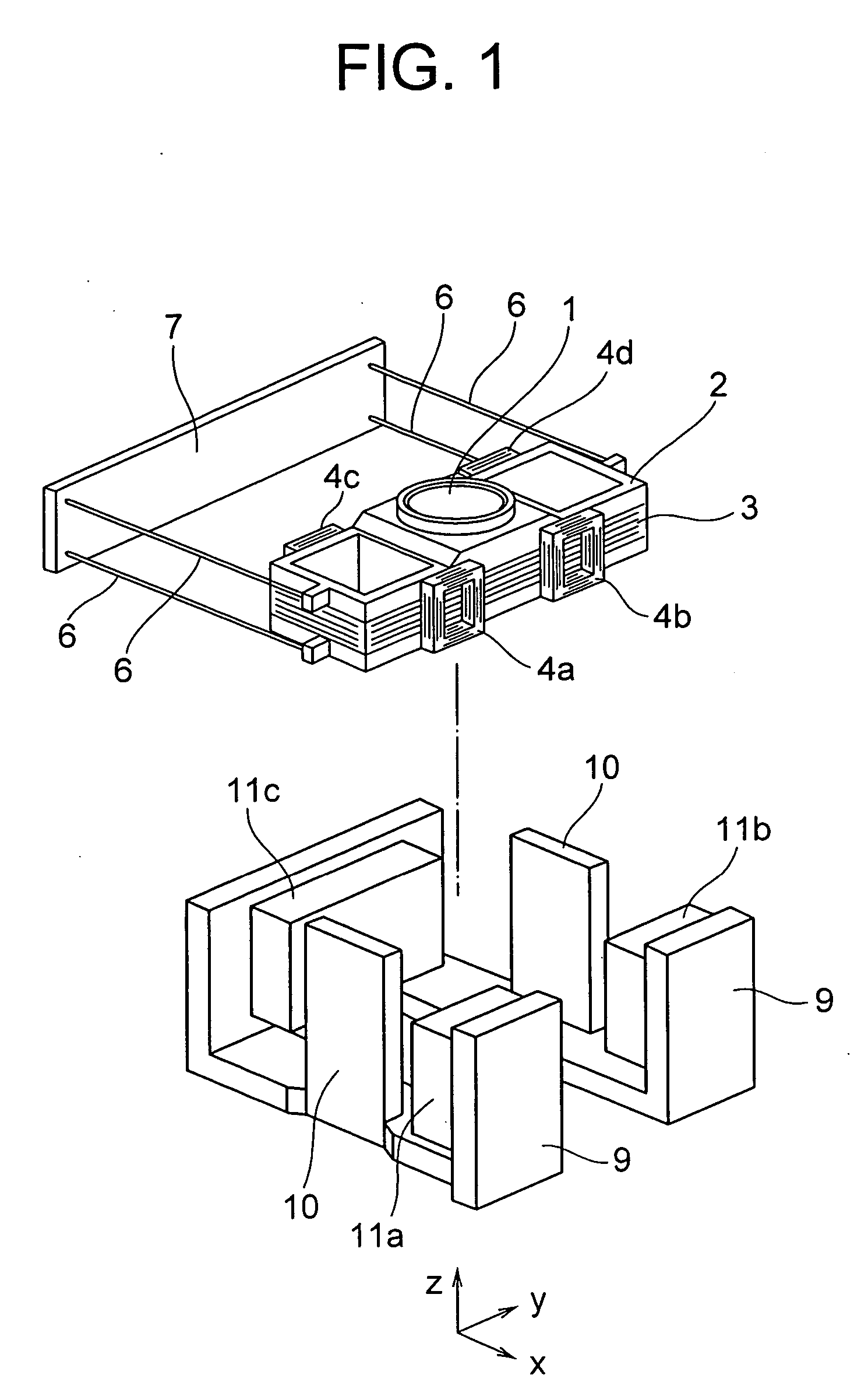
[0021]FIG. 1 is an exploded perspective view for illustrating the configuration of an embodiment of the objective-lens driving apparatus. In FIG. 1, the x-axis direction is the tangent direction of a not-illustrated disk. The y-axis direction is the tracking direction, i.e., the radial direction of the disk. The z-axis direction is the focusing direction, i.e., the optical-axis direction of an objective lens 1.

[0022] A focusing coil 3, i.e., a driving coil, is wound around a lens holder 2 for holding the objective lens 1. Also, four tracking coils 4a, 4b, 4c and 4d are mounted onto the lens holder 2. One ends of w...


PUM

PropertyMeasurementUnit
polaritiesaaaaaaaaaa
electromagneticaaaaaaaaaa
magnetic fluxaaaaaaaaaa

Abstract

An objective-lens driving apparatus, includes an objective lens for converging light on a recording surface of an optical disk, a focusing coil having four edges for enclosing the objective lens, and two pairs of permanent magnets. The two pairs of permanent magnets are arranged so that polarities thereof are identical toward the focusing coil, with one pair of the permanent magnets arranged so as to be opposed to one edge of the focusing coil, and another pair of the permanent magnets arranged so as to be opposed to another edge of the focusing coil which is opposite to the one edge of focusing coil. An interval between two permanent magnets constituting the one pair of the permanent magnets is narrower than an interval between two permanent magnets constituting the another pair of the permanent magnets.

Description

CROSS REFERENCE TO RELATED APPLICATION [0001] This application is a continuation of U.S. application Ser. No. 10 / 714,944, filed Nov. 18, 2003, the contents of which are incorporated herein by reference.BACKGROUND OF THE INVENTION [0002] The present invention relates to an objective-lens driving apparatus for use in an optical disk apparatus for recording information on the recording surface of an optical disk or for reading the information recorded thereon. [0003] In an optical disk apparatus for recording information on a disk-shaped recording medium or for reading and reproducing the information recorded thereon, an objective-lens driving apparatus is an apparatus for driving an objective lens in the focusing direction (i.e., the direction in which the objective lens comes closer to / goes away from the recording surface of the optical disk) and in the tracking direction (i.e., the radial direction of the disk). Here, the objective lens light-converges light on the optical-disk reco...

Claims


Application Information

Patent Timeline
Patent Type & Authority Applications(United States)
IPC IPC(8): G11B7/00G11B7/09G11B7/095
CPCG11B7/093G11B7/0956G11B7/0935G11B7/0933
Inventor KIMURA, KATSUHIKOKATOU, SEIICHIOGASAWARA, HIROSHI
Owner HITACHI MEDIA ELECTORONICS CO LTD
Learn More