Replaceable annular electrode for transgenic

a technology of annular electrode and transgenic body, which is applied in the field of annular electrode, can solve the problems of inconvenient operation of conventional electroporation apparatus, and plant tissue injury in cramped tubular electrod

Inactive Publication Date: 2007-01-04
CHEN JUNNE JIH +3
View PDF4 Cites 3 Cited by
  • Summary
  • Abstract
  • Description
  • Claims
  • Application Information

AI Technical Summary

Benefits of technology

[0008] To achieve the objective, the annular electrode in accordance with the present invention comprises a hand-held electrode seat having multiple metal rods downward extending from the hand-held seat. An electrode ring is secured on a free end of each of the multiple metal rods. A first electrode rod centrally downward extends from the hand-held seat and a sleeve is sleeved on the first electrode rod. The sleeve is secured on the first electrode rod by bolts. The sleeve has a second electrode rod centrally downward extending therefrom and the second electrode rod is electrically connected to the first electrode rod when the sleeve is secured on the first electrode rod such that the second electrode rod can be replaced to have various lengths and diameters such that annular electrode can use different distances between the second electrode rod and the electrode ring to make different obvious electric shock effects.

Problems solved by technology

However, the conventional electroporation apparatus is unsuitable to a great plant tissue and the room in the tubular electrode is cramped such that the plant tissue may be hurt in the cramped tubular electrode.
In addition, the operation of the conventional electroporation apparatus takes a lot of time, costs a lot of money and the tubular electrode can not be repeatedly used.
Furthermore, the aluminum foil conducting end is easily oxidized and causes poison material.

Method used


Image

  • Replaceable annular electrode for transgenic
  • Replaceable annular electrode for transgenic
  • Replaceable annular electrode for transgenic

Examples


Embodiment Construction

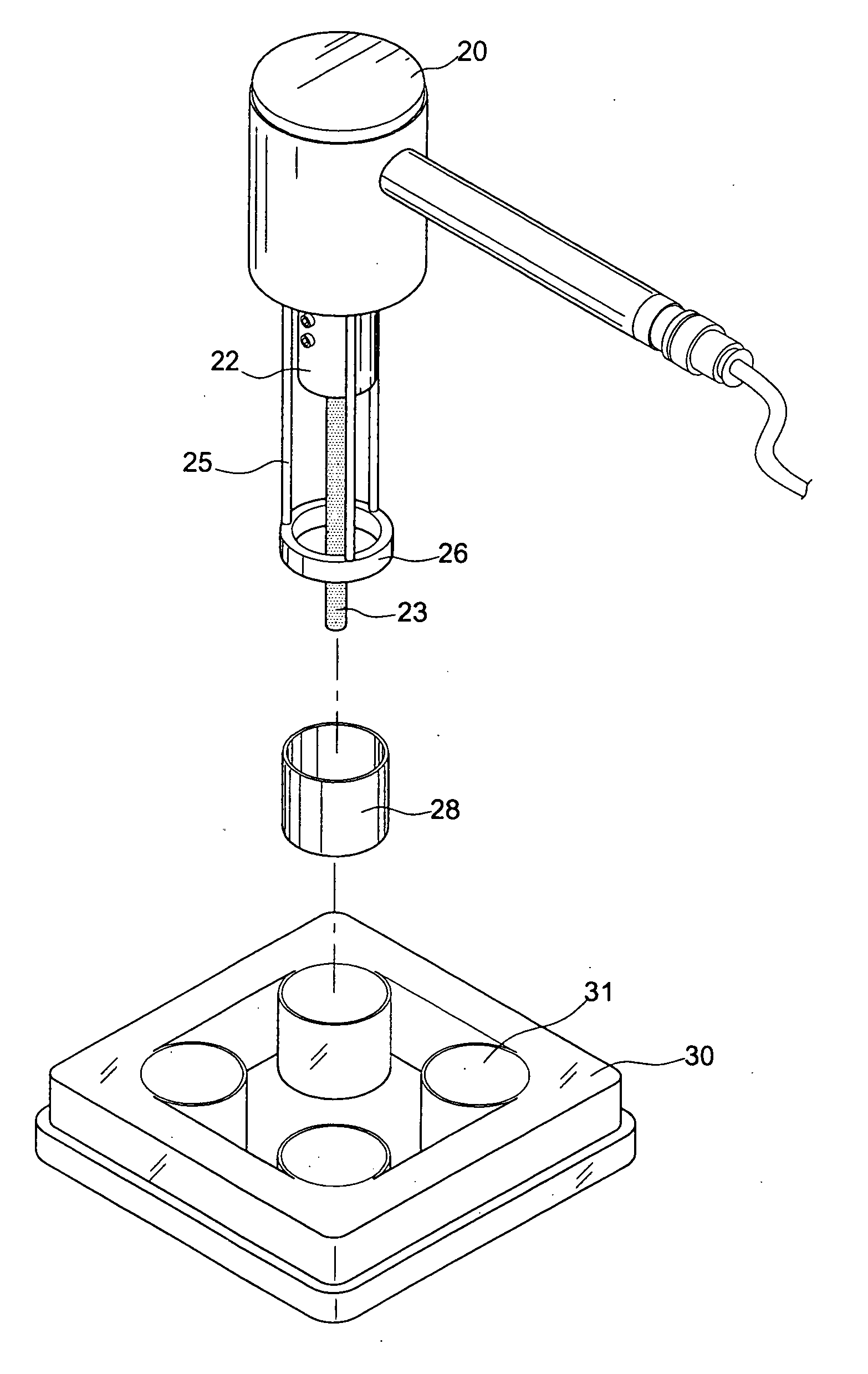
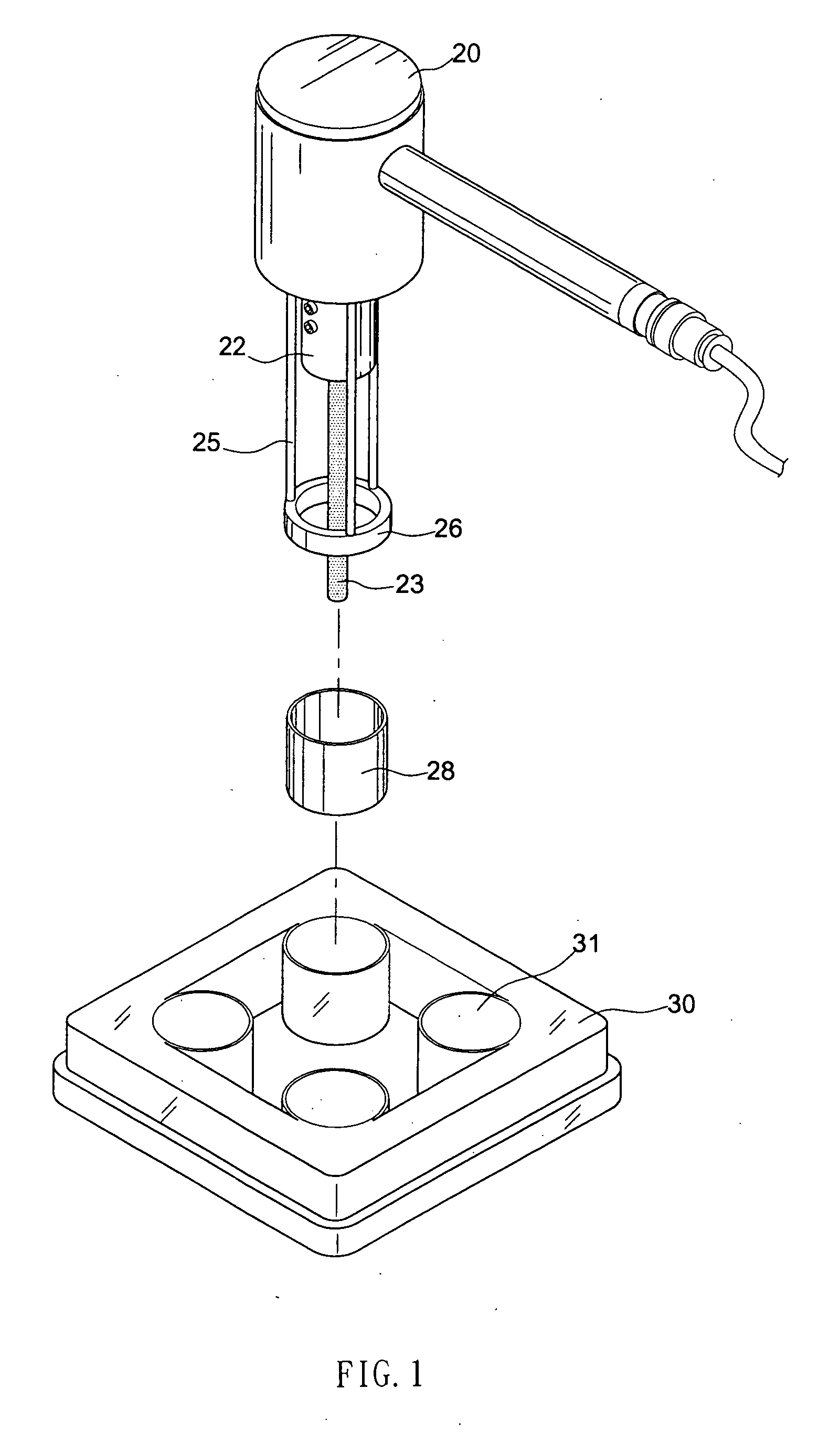
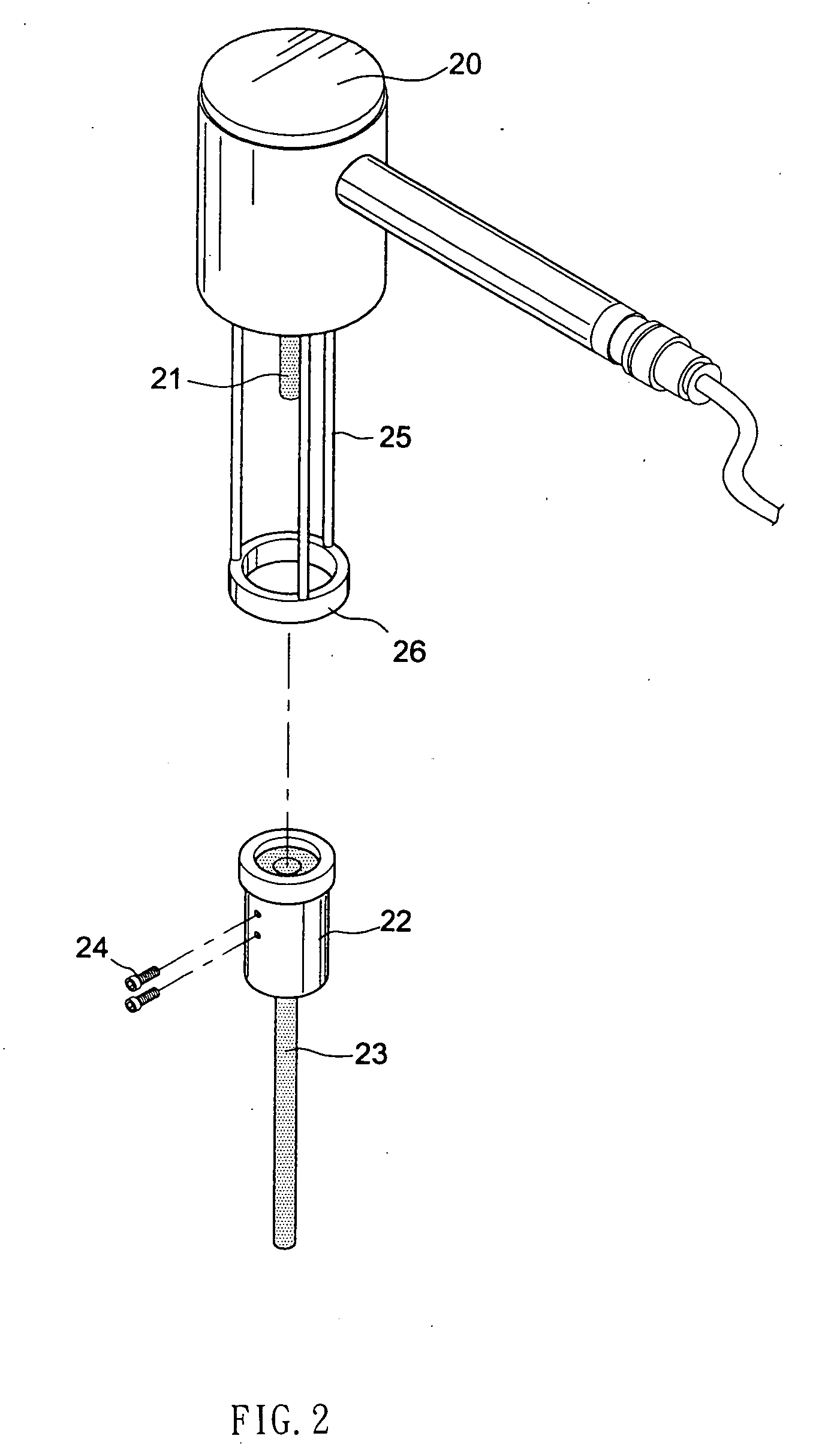
[0014] Referring to the drawings and initially to FIGS. 1-4, a replaceable annular electrode for transgenic in accordance with the present invention comprises a hand-held electrode seat (20) having multiple metal rods (25) downward extending therefrom. An electrode ring (26) is secured on a free end of each of the multiple metal rods (25). A first electrode rod (21) centrally downward extends from the hand-held seat (20) and a sleeve (22) is sleeved on the first electrode rod (21). The sleeve (22) is secured on the first electrode rod (21) by bolts (24). The sleeve (22) has a second electrode rod (23) centrally downward extending therefrom and the second electrode rod (23) is electrically connected to the first electrode rod (21) when the sleeve (22) is secured on the first electrode rod (21). Consequently, the second electrode rod (23) of the present invention can be replaced to have various lengths and diameters such that the present invention can use different distances between t...


PUM

PropertyMeasurementUnit
lengthsaaaaaaaaaa
diametersaaaaaaaaaa
electric conductivityaaaaaaaaaa

Abstract

A replaceable annular electrode for transgenic includes a hand-held electrode seat having multiple metal rods downward extending from the hand-held seat. An electrode ring is secured on a free end of each of the multiple metal rods. A first electrode rod centrally downward extends from the hand-held seat and a sleeve is sleeved on the first electrode rod. The sleeve is secured on the first electrode rod by bolts. The sleeve has a second electrode rod centrally downward extending therefrom and the second electrode rod is electrically connected to the first electrode rod when the sleeve is secured on the first electrode rod such that the second electrode rod can be replaced to have various lengths and diameters such that annular electrode can use different distances between the second electrode rod and the electrode ring to make different obvious electric shock effects.

Description

BACKGROUND OF THE INVENTION [0001] 1. Field of the Invention [0002] The present invention relates to an annular electrode, and more particularly to a replaceable annular electrode that is provided for transgenic. [0003] 2. Description of Related Art [0004] The known plant transgenic method includes tubularlarrium-mediated transformation, gene gun, electroporation, microinjection, heat shock, pollen tube pathway, etc. The electroporation exposes cells under a condition of a twinkle high-voltage discharge. As a result, multiple tiny bores are temporarily defined in the cell membrane and the plasmid deoxyribonucleic acid (DNA) can get into the cell for achieving the purpose of transgenic. However, the conventional electroporation apparatus usually uses disposable tubular electrode and the plant tissue solution is received in the tubular electrode. In addition, a lower end of the tubular electrode is clamped by an electrode clamp. [0005] However, the conventional electroporation apparat...

Claims


Application Information

Patent Timeline
Patent Type & Authority Applications(United States)
IPC IPC(8): C12M1/42
CPCC12M35/02
Inventor CHEN, JUNNE-JIHWU, FANG-SHENGSUN, YUNG-WEISHEN, HAN-TSU
Owner CHEN JUNNE JIH
Why Eureka
Try Eureka