Wiring harness excess length absorbing device
a technology of excess length and absorbing device, which is applied in the direction of coupling device connection, insulated conductor, and relatively moving parts. it can solve the problems of difficult to set the extending and contracting stroke (excess length absorption length), reduce the number of components and production costs, and facilitate the wear down of relevant portions. it can achieve the effect of improving disassembly properties and reducing production costs
- Summary
- Abstract
- Description
- Claims
- Application Information
AI Technical Summary
Benefits of technology
Problems solved by technology
Method used
Image
Examples
first embodiment
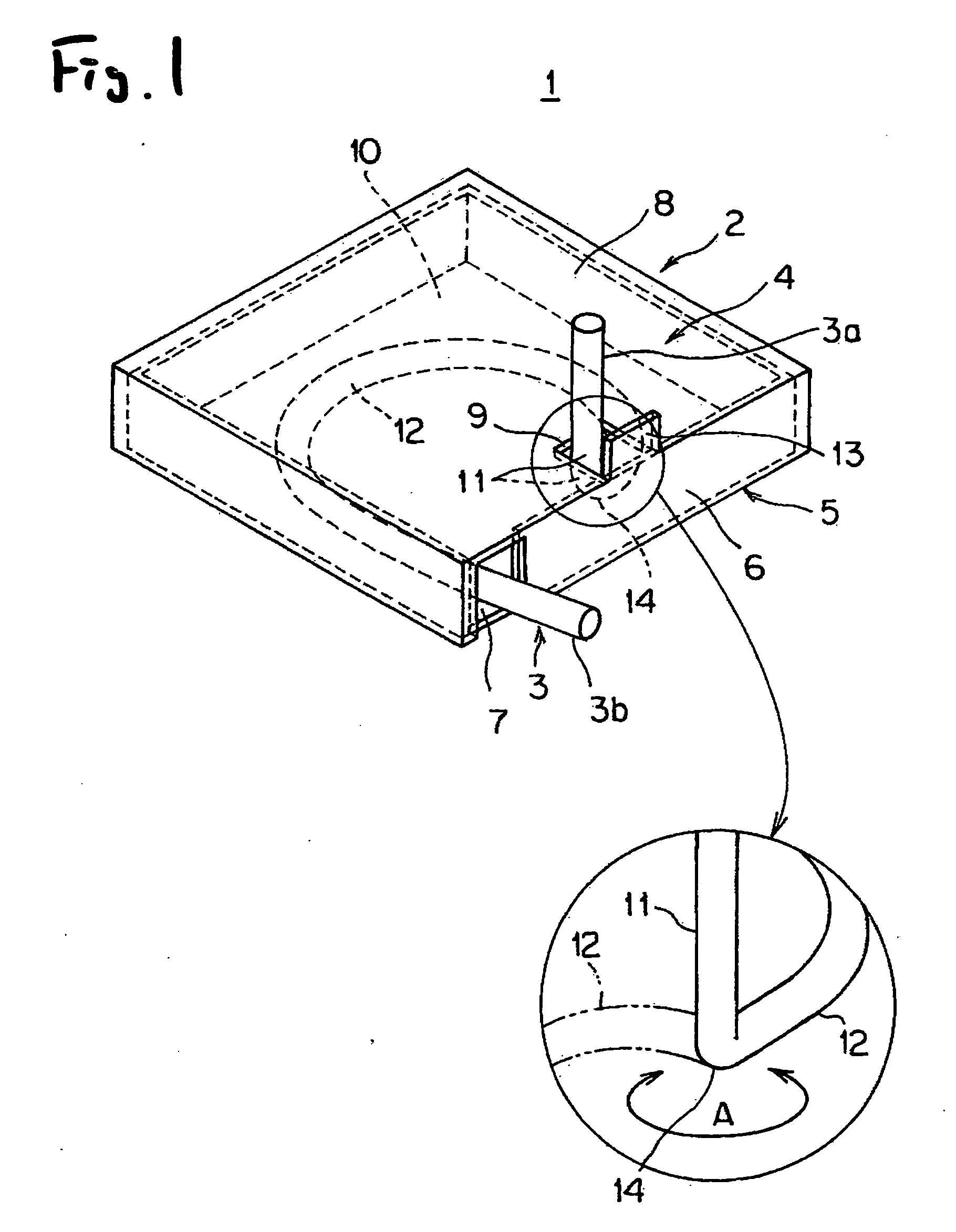
[0078]FIG. 1 shows a wiring harness excess length absorbing device according to the invention.
[0079] This wiring harness excess length absorbing device (apparatus) 1 is such as to include a rectangular box-shaped thin case (a wiring harness accommodating portion) 2 and a wiring harness 3 which is formed into a substantially semi-annular shape (an incompletely annular shape) for accommodation within the case.
[0080] The case 2 is made from a synthetic resin material and is made up of an upper cover 4 and a lower case main body 5. The case main body 5 is surrounded by front, rear, left and right wall portions and a lower wall portion to thereby have a wiring harness accommodating portion inside thereof. The cover 4 is made up of front, rear, left and right wall portions and an upper wall portion and is covered externally over the case main body 5 to thereby be locked on the case main body 5 by means of a locking member (not shown) made up of a combination of locking frame piece and en...
second embodiment
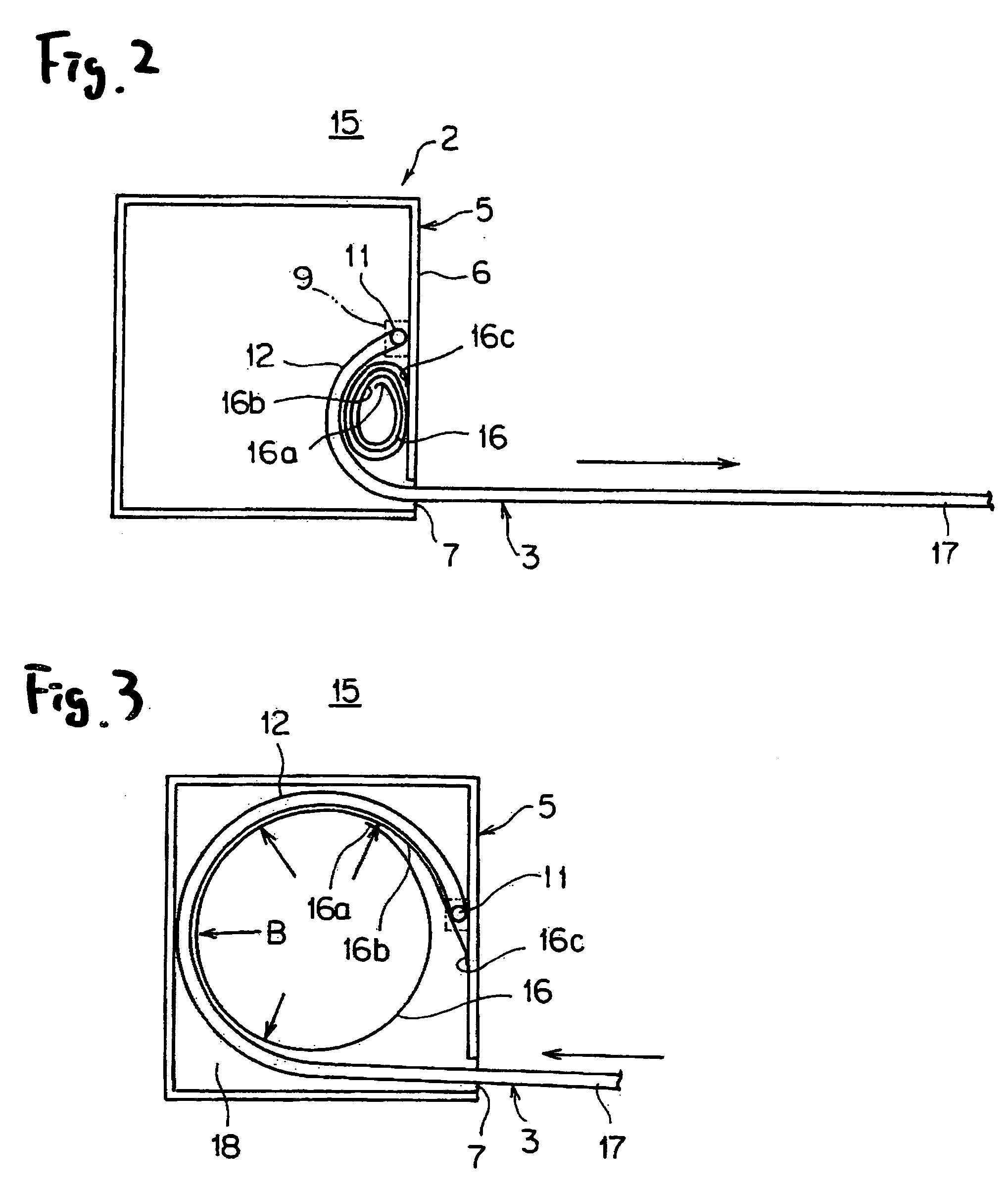
[0090] FIGS. 2 to 3 show a wiring harness excess length absorbing device (apparatus) according to the invention.
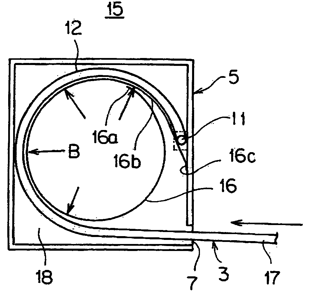
[0091] This wiring harness excess length absorbing device (apparatus) 15 is such that a power spiral spring (the spring member or the biasing member) is added to the wiring harness excess length absorbing device (apparatus) 1 shown in FIG. 1, and the other configurations are similar to those of the wiring harness excess length absorbing device (apparatus) 1 shown in FIG. 1. Like reference numerals are imparted to like constituent members to those shown in FIG. 1, and the description thereof will be omitted here. FIGS. 2 to 3 show a state resulting when looking down at a case 2 with its cover 4 (FIG. 1) removed.
[0092] The spiral spring 16 is such as to result by winding a metallic leaf spring into a spiral shape, and an outer end of the spiral spring 16 is fixed to the vicinity of a straight portion 11 of a wiring harness 3 within the case, whereas an inner end 16a of the ...
third embodiment
[0099] FIGS. 4 to 5 are such as to show a wiring harness excess length absorbing device (apparatus) according to the invention.
[0100] This wiring harness excess length absorbing device (apparatus) 21 is such that a guide arm (the wiring harness guide member) 23 is provided rotatably in a case (the wiring harness accommodating portion) 22, the guide are 23 is biased towards the inside of the case by a twisting coil spring (the spring member or biasing member) 24 and a wiring harness 3 is laid out along the guide arm 23.
[0101] The guide arm 23, as well as the case 22, is made from a synthetic resin material and is made up of a straight rod portion 25 and a semi-circular head portion 26 formed integrally at a distal end of the rod portion 25. The head portion 26 is disposed in such a manner as to be offset sideways relative to the distal end of the rod portion 25, and a side 25a of the rod portion 25 continues smoothly to an arc-shaped outer circumferential surface 26a of the head por...
PUM
 Abstract
Description
Claims
Application Information
 - R&D
- Intellectual Property
- Life Sciences
- Materials
- Tech Scout
- Unparalleled Data Quality
- Higher Quality Content
- 60% Fewer Hallucinations
Browse by: Latest US Patents, China's latest patents, Technical Efficacy Thesaurus, Application Domain, Technology Topic, Popular Technical Reports.
© 2025 PatSnap. All rights reserved.Legal|Privacy policy|Modern Slavery Act Transparency Statement|Sitemap|About US| Contact US: help@patsnap.com


