
Achromatic Polarization Switches

a technology of achromatic polarization and switches, applied in the field of achromatic polarization switches, can solve the problems of high hardware cost, crude image formation, and added cost to the presentation relative to a linear polarized system

Active Publication Date: 2006-12-28
REAID INC
View PDF38 Cites 238 Cited by
  • Summary
  • Abstract
  • Description
  • Claims
  • Application Information

AI Technical Summary

Benefits of technology

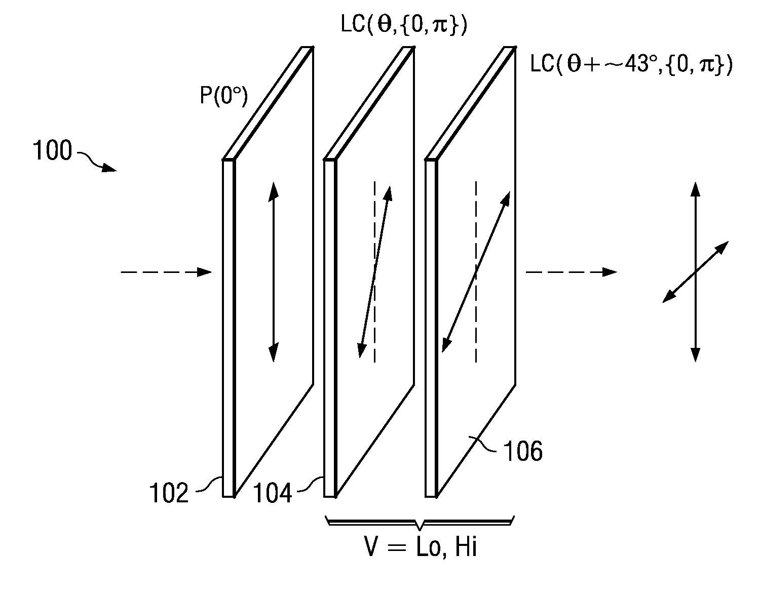
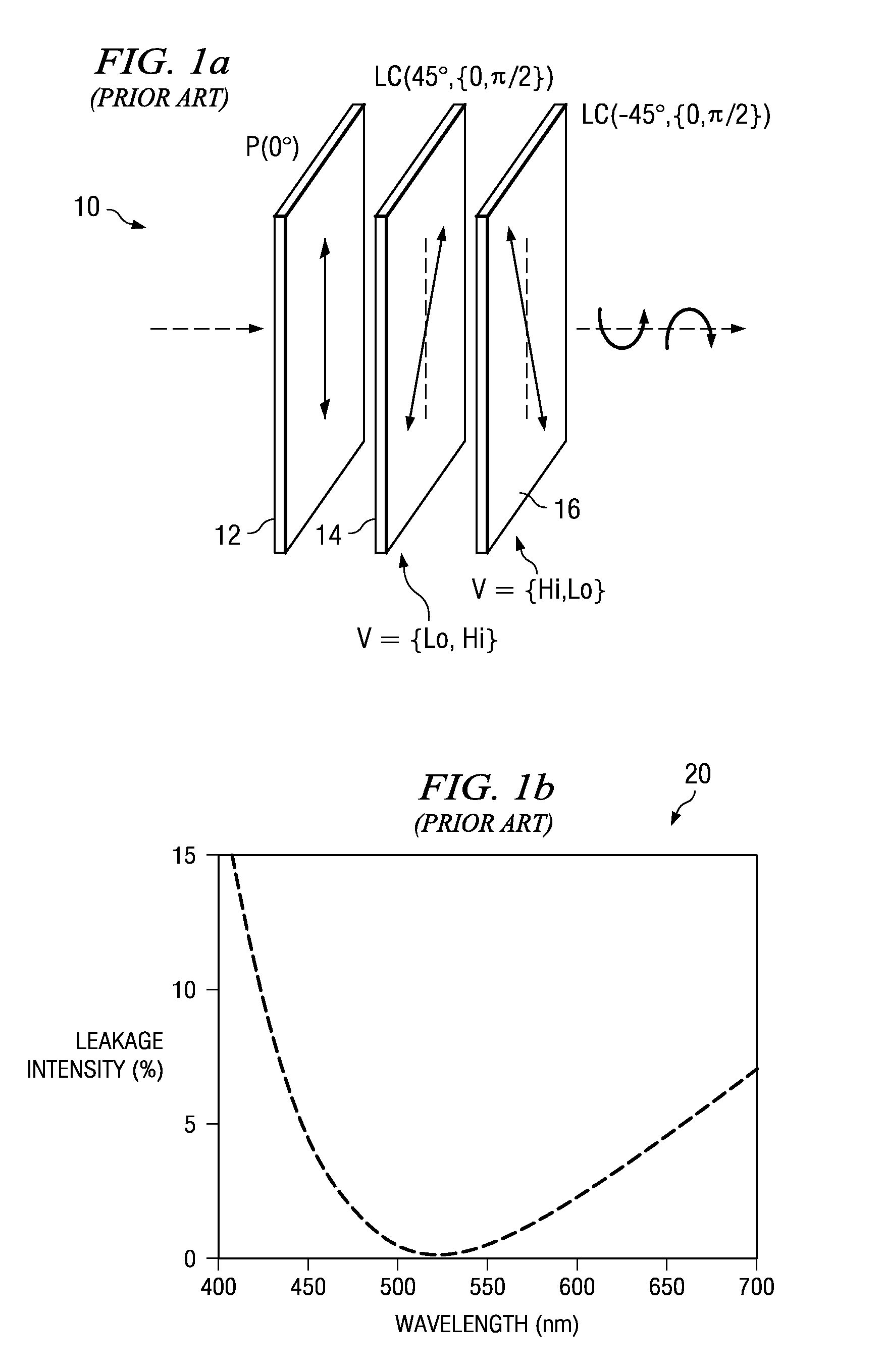
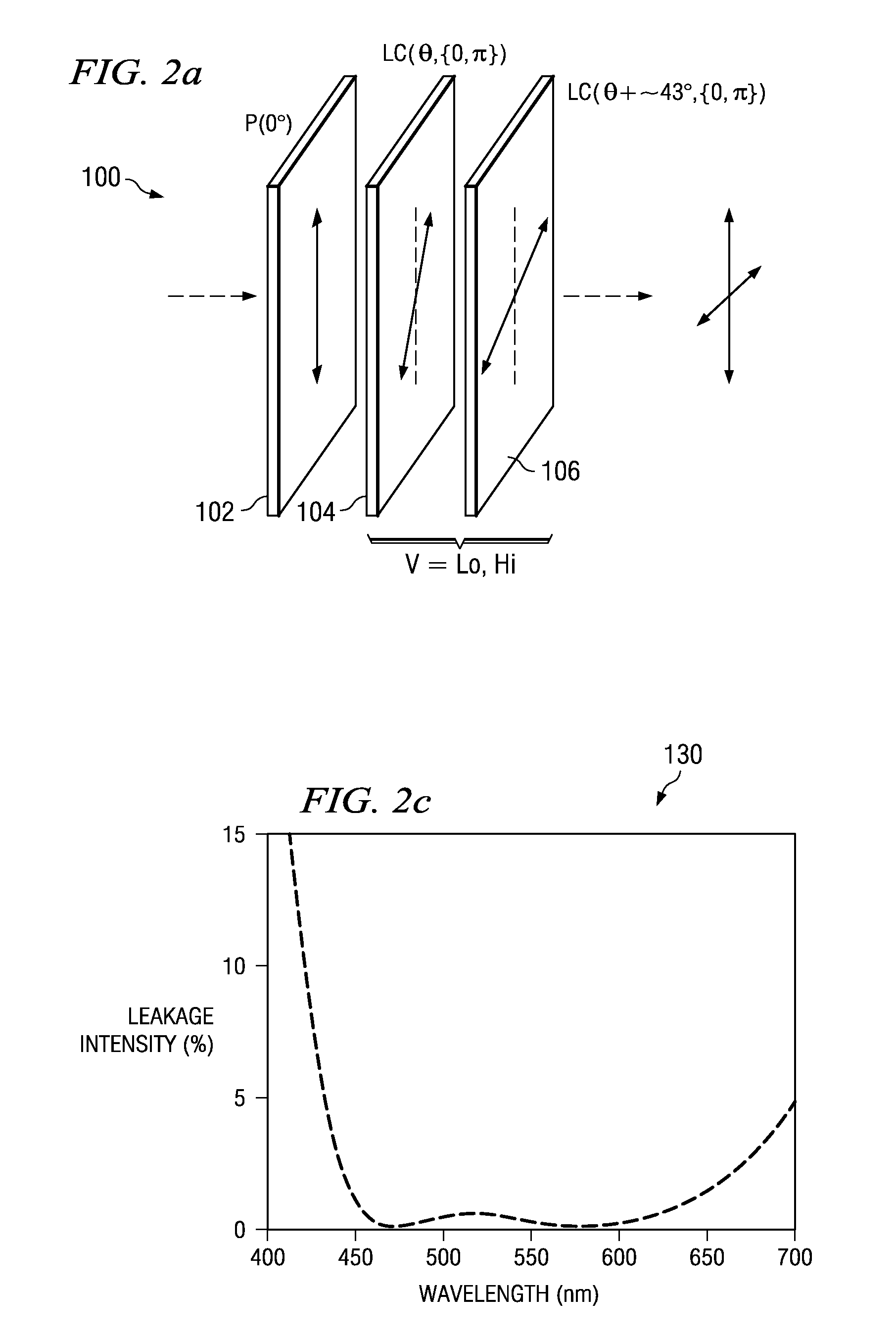
The patent describes an achromatic polarization switch (APS) that can create different polarization states for visible light. The APS uses a special liquid crystal material and a half-wavelength retarder to create two different polarization states that are perpendicular to each other. The APS can be combined with other polarization elements to create even more embodiments. The patent also describes a projection system that uses the APS to create stereoscopic imaging by alternating the output polarization state of a display in synchronization with time-sequential images from a projector. The viewer then uses appropriate eyewear to analyze the images and create a 3D image sensation.

Problems solved by technology

Although, these approaches more closely reproduce true three-dimensional images, they are very demanding of hardware and at present can only form very crude images.
Encoding the stereoscopic images in the same color bands can yield a three-dimensional sensation although the observable difference in what the eyes see causes fatigue.
Furthermore the eyewear has to be of a matching circularly polarized form adding cost to a presentation relative to a linear polarized system.
However, under this condition the correct right eye image is deficient of red and blue light when compared to the original image requiring color balance and associated light loss.
Such chromatic behavior that is wavelength-dependent and influenced by head tilt is undesirable as it affects the viewing experience.

Method used


Image

  • Achromatic Polarization Switches
  • Achromatic Polarization Switches
  • Achromatic Polarization Switches

Examples


fourth embodiment

[0054]FIG. 6 illustrates an APS 600. This exemplary embodiment of APS 600 includes compensation elements, where θ=8°. APS 600 includes an input polarizer 602, first retarder stack 603, first LC pi-cell 610, second retarder stack 611, second LC pi-cell 622, and third retarder stack 623.

[0055] In this fourth embodiment, a first retarder stack 603 is located on an optical path between input polarizer 602 and first LC pi-cell 610, and includes biaxial retarder 604 with R(8°, λ / 2), uniaxial retarder 606 with R(38.5°, Δnd / 2), and uniaxial retarder 608 with R(128.5°, Δnd / 2). Second retarder stack 611 is located on an optical path between first LC pi-cell 610 and second LC pi-cell 622, and includes uniaxial retarder 612 with R(128.5°, Δnd / 2+ΔΓ), uniaxial retarder 614 with R(38.5°, Δnd / 2), biaxial retarder 616 with R(−74°, λ / 2), uniaxial retarder 618 with R(38.5°, Δnd / 2), and uniaxial retarder 620 with R(128.5°, Δnd / 2+ΔΓ). Third retarder stack 623 is located on an optical path after second L...

fifth embodiment

[0063] In-plane switching of a half wave retarder can provide achromatic properties as it can be considered equivalent to two ZTN cells oriented at the in-plane switching angle with respect to each other. Solutions have already been discussed in commonly assigned U.S. Pat. No. 6,046,786 issued Apr. 4, 2000 (Sharp et al.). In situations where symmetric behavior is desired, various embodiments exist that minimize the average leakage over the visible spectrum for the two blocking states. For example, FIG. 7a illustrates an APS 700, providing symmetry between output polarization states, thereby aligning the in-plane LC switches optic axes symmetrically either side of the axis bisecting the desired output linear polarization axes. Accordingly, the input polarization state may then be transformed between elliptical states whose major axis is also along this bisecting axis.

[0064] In this exemplary embodiment, APS 700 includes a linear polarizer 702, an input retarder 704, and an in-plane s...


PUM


Abstract

An achromatic polarization switch (APS) acts on linear polarized light to provide orthogonal polarized output states over a range of visible wavelengths. In a first switching state, the APS is operable to pass light of a first polarization state therethrough. In a second switching state, the APS is operable to transform light passing therethrough to a substantially orthogonal second polarization state. Used in conjunction with orthogonal analyzing eyewear, left and right eye images are time-sequentially modulated in orthogonal polarization states by the APS to yield a stereoscopic 3D image sensation.

Description

CROSS REFERENCE TO RELATED APPLICATIONS [0001] This application claims priority to Provisional Application No. 60 / 761,222, filed Jan. 23, 2006. The entire disclosure of the Provisional Application is incorporated by reference herein.TECHNICAL FIELD [0002] This disclosure relates generally to achromatic polarization switches (APSs), and more particularly relates to APSs that modulate a visible spectral range of light between orthogonal polarization states. Further, the APSs are directed for use in stereoscopic display systems that modulate the polarization of left and right eye images to provide stereoscopic 3D imagery. BACKGROUND [0003] Three-dimensional displays can be of several forms. Those such as holographic displays that form an exact optical representation of three-dimensional objects through phase and amplitude modulation of light. Others recreate three-dimensional information using volume displays such as a series of synchronized modulating two-dimensional screens. Although...

Claims


Application Information

Patent Timeline
Patent Type & Authority Applications(United States)
IPC IPC(8): G02B27/26G02B30/25
CPCG02B27/2264G02B27/26G02F1/0136G02F2203/07G02F1/1347G02F2203/04G02F1/13306G02B30/24G02B30/25
Inventor ROBINSON, MICHAEL G.SHARP, GARY D.
Owner REAID INC
Learn More