
Longitudinal dilator

a dilator and longitudinal technology, applied in the field of surgical instruments, can solve problems such as unfavorable tunnels, and achieve the effects of avoiding repetitive motion, uniform tissue dilation, and avoiding repetitive actuation and high level forces

Inactive Publication Date: 2006-12-21
MAQUET CARDIOVASCULAR LLC
View PDF99 Cites 104 Cited by
  • Summary
  • Abstract
  • Description
  • Claims
  • Application Information

AI Technical Summary

Benefits of technology

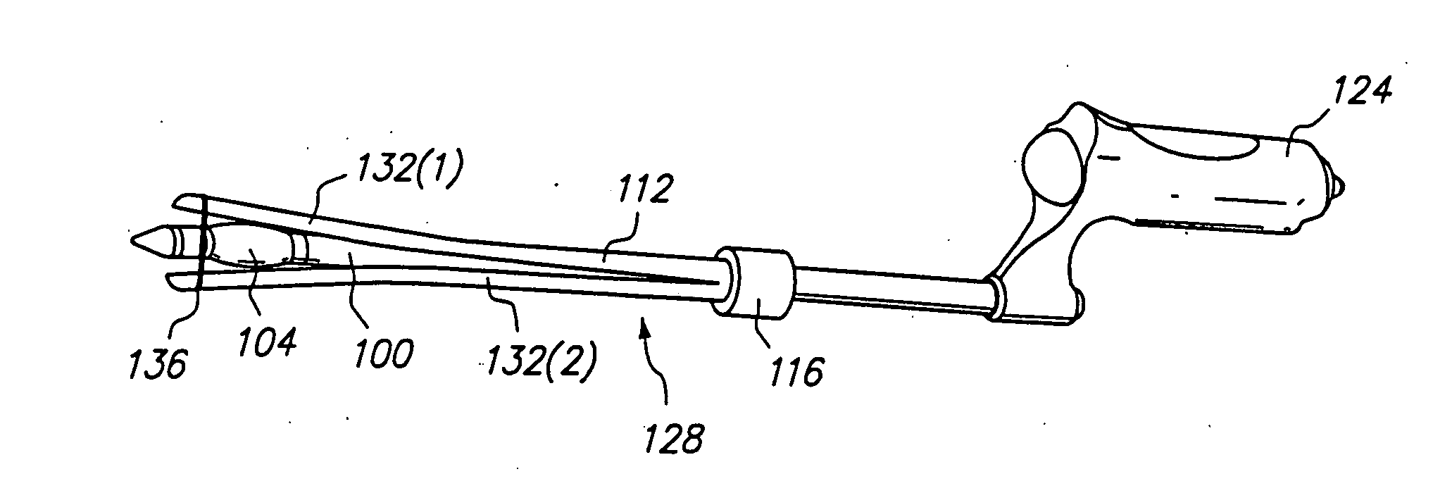
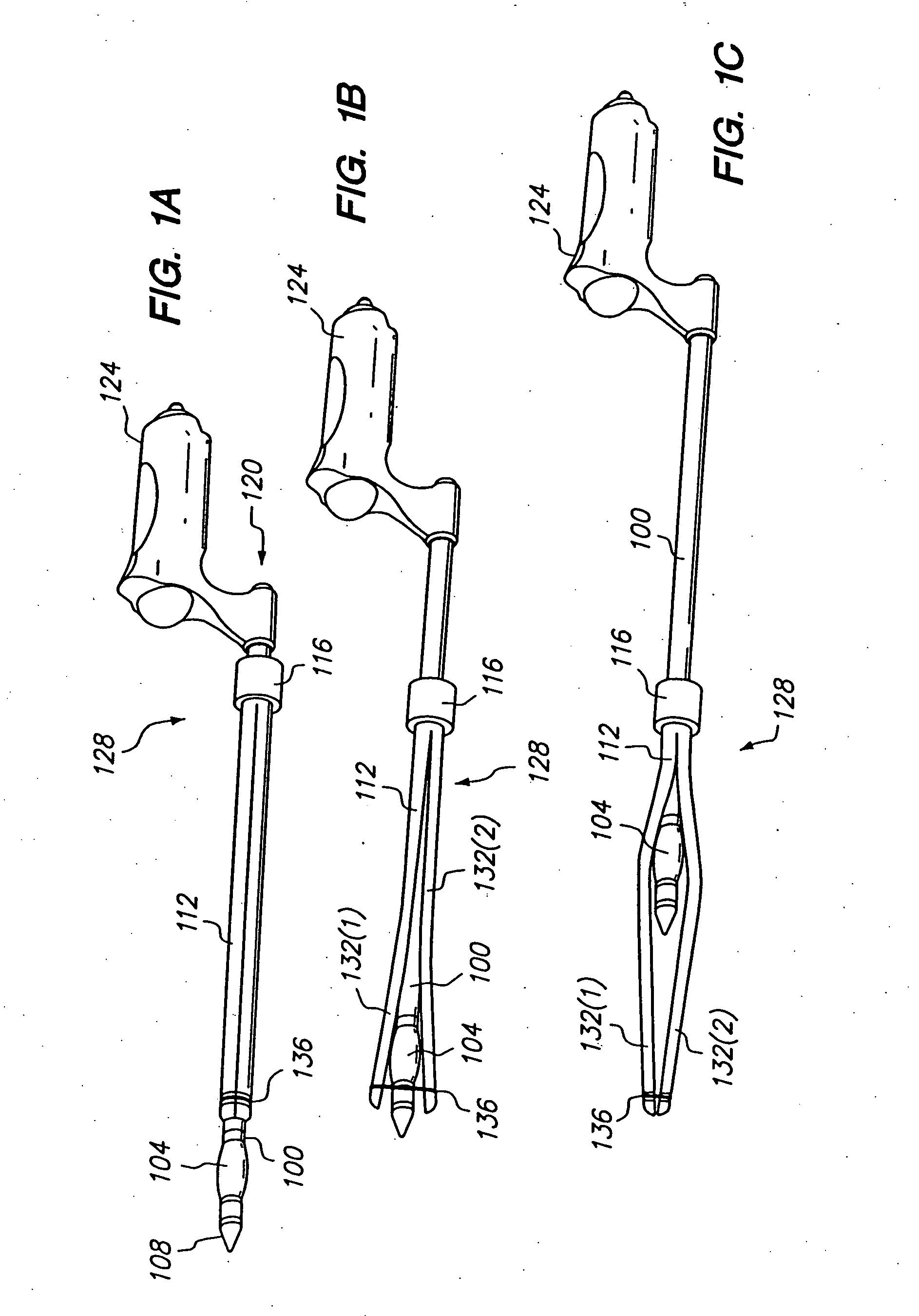
[0004] Apparatus and method according to the present invention perform uniform dilation of tissue while avoiding repetitive actuations and high level forces applied by the user. In a preferred embodiment, a tissue expanding device is pulled longitudinally along an expansible sheath to dilate an extravascular tunnel. In one embodiment, the tissue expansion device is positioned immediately proximal to a transparent tapered tip of a cannula and is formed as a wedge or olive. The distal end of the expansible sheath is compressed against the outer surface of the cannula by a resilient connector, and, in one embodiment, the expansible sheath ends in a solid sleeve proximally. Then, as the tissue expansion device is retracted through the expansible sheath, the resilient connector expands outwardly to permit the tissue expansion device to be retracted into the expansible sheath. As the tissue expansion device is moved toward the proximal end of the cannula through the expansible sheath, the sheath expands concurrently with it, providing an even dilation of the surrounding tissue. The tissue dilation may be obtained through one smooth motion of pulling back on the inner cannula, thus avoiding repetitive motions. The sheath is preferably made of a rigid or semi-rigid material and the tissue expansion device has an enlarged maximal dimension. The force exerted on surrounding tissue by the expansion of the sheath as a result of the movement of the tissue expansion device within the sheath is therefore sufficiently high to provide adequate dilation of the surrounding tissue.

Problems solved by technology

This repeated motion may tire the hand of a surgeon performing the procedure, and, further, stepwise dilation may result in formation of an uneven tunnel, with an irregular inner contour.

Method used


Image

  • Longitudinal dilator
  • Longitudinal dilator
  • Longitudinal dilator

Examples


Embodiment Construction

[0015]FIG. 1A is a perspective view of a longitudinal mechanical dilator 128 in accordance with the present invention. The dilator 128 preferably comprises an inner cannula 100 and an outer expansible sheath 112. A tissue expansion device 104 is disposed on the distal end of the inner cannula 100. In one embodiment, the outer expansible sheath 112 is preferably split longitudinally into two shells 132. Alternatively, the outer expansible sheath 112 is comprised of a flexible material that expands upon moving the tissue expansion device 104 within the sheath 112. In one embodiment, the distal end of the outer expansible sheath 112 is compressed against the outer surface of the inner cannula 100 by a resilient connector 136. The proximal end of the outer expansible sheath 112 preferably includes an integrated segment, for example, within a handle 116. Thus, upon retracting the tissue expansion device 104 through the distal end of the outer expansible sheath 112, as shown in FIG. 1B, t...


PUM


Abstract

Apparatus and method for dilation of tissue utilize a tissue expansion device positioned on an inner cannula with an outer overlying expansive sheath that expands upon translation of the tissue expansion device therethrough. The tissue expansion device may be an olive or wedge formed near the tip of the cannula, and the expansible sheath includes two elongated shells that are fixably attached near proximal ends, and that are resiliently connected near distal ends. Translating the tissue expansion device through the expansible sheath expands the dimension of the shells to provide even dilation of surrounding tissue. Additionally, tissue dilation is performed in one continuous motion of retracting the inner cannula through the expansible sheath or pushing the tissue expansion device through the expansible sheath. The outer expansible sheath may be removed from the inner cannula to provide a dissection instrument having minimal outer diameter. The tissue expansion device may provide two stage expansion from a minimal outer dimension in one configuration to a second larger outer dimension in response to an applied axial force to provide enhanced tissue dilation.

Description

RELATED APPLICATIONS [0001] This application is a continuation of U.S. patent application Ser. No. 10 / 006,321 filed on Dec. 4, 2001, entitled “Longitudinal Dilator and Method”, which is a divisional of U.S. patent application Ser. No. 09 / 915,695, entitled “Longitudinal Dilator and Method”, filed Jul. 25, 2001, now U.S. Pat. No. 6,428,556, which is a divisional application of U.S. patent application Ser. No. 09 / 645,473, entitled “Longitudinal Dilator and Method, filed on Aug. 24, 2000, now U.S. Pat. No. 6,607,547, which claims priority from U.S. provisional patent application No. 60 / 150,737, entitled “Longitudinal Mechanical Dilator for Vessel Harvesting”, filed on Aug. 25, 1999, and the subject matter hereof is related to U.S. provisional application Ser. No. 60 / 148,130, entitled “Apparatus and Method for Endoscopic Pericardial Access”, filed on Aug. 9, 1999, and U.S. patent application Ser. No. 09 / 635,721, entitled “Apparatus for Endoscopic Access”, filed on Aug. 9, 2000, all of wh...

Claims


Application Information

Patent Timeline
IPC IPC(8): A61B1/00A61B1/04
CPCA61B2017/320044A61M29/02A61B2017/320048
Inventor CHIN, ALBERT K.
Owner MAQUET CARDIOVASCULAR LLC
Learn More