
Illuminating membrane switch and illuminating keypad using the same

a technology of illuminating membrane switch and illuminating keypad, which is applied in the direction of instruments, contact mechanisms, legends, etc., can solve the problems of increasing the thickness of the key cap b>12/b> and affecting the design of the keyboard structur

Inactive Publication Date: 2006-12-21
FIRST LITE CORP
View PDF3 Cites 12 Cited by
  • Summary
  • Abstract
  • Description
  • Claims
  • Application Information

AI Technical Summary

Benefits of technology

[0009] The second objective of the present invention is to provide an illuminating membrane switch acceptable for the structure of a conventional keyboard. The housing, key caps and key actuators of the conventional keyboard do not need to be redesigned.
[0010] In order to achieve the objective, the present invention discloses an illuminating membrane switch and illuminating keyboard using the same. The illuminating membrane switch comprises an upper membrane sheet, an electroluminescent device and a lower membrane sheet. The electroluminescent device is interposed between the upper membrane sheet and lower membrane sheet on which switch circuits are printed. In addition to emitting rays through the upper membrane sheet, the electroluminescent device has a plurality of openings allowing the switch circuits of them to contact each other. The keyboard utilizes the illuminating membrane switch to detect any input of keystroke. On the other hand, the keyboard can light up the symbols on the surfaces of key caps for a user to identify the function or alphabetic input of each key cap.

Problems solved by technology

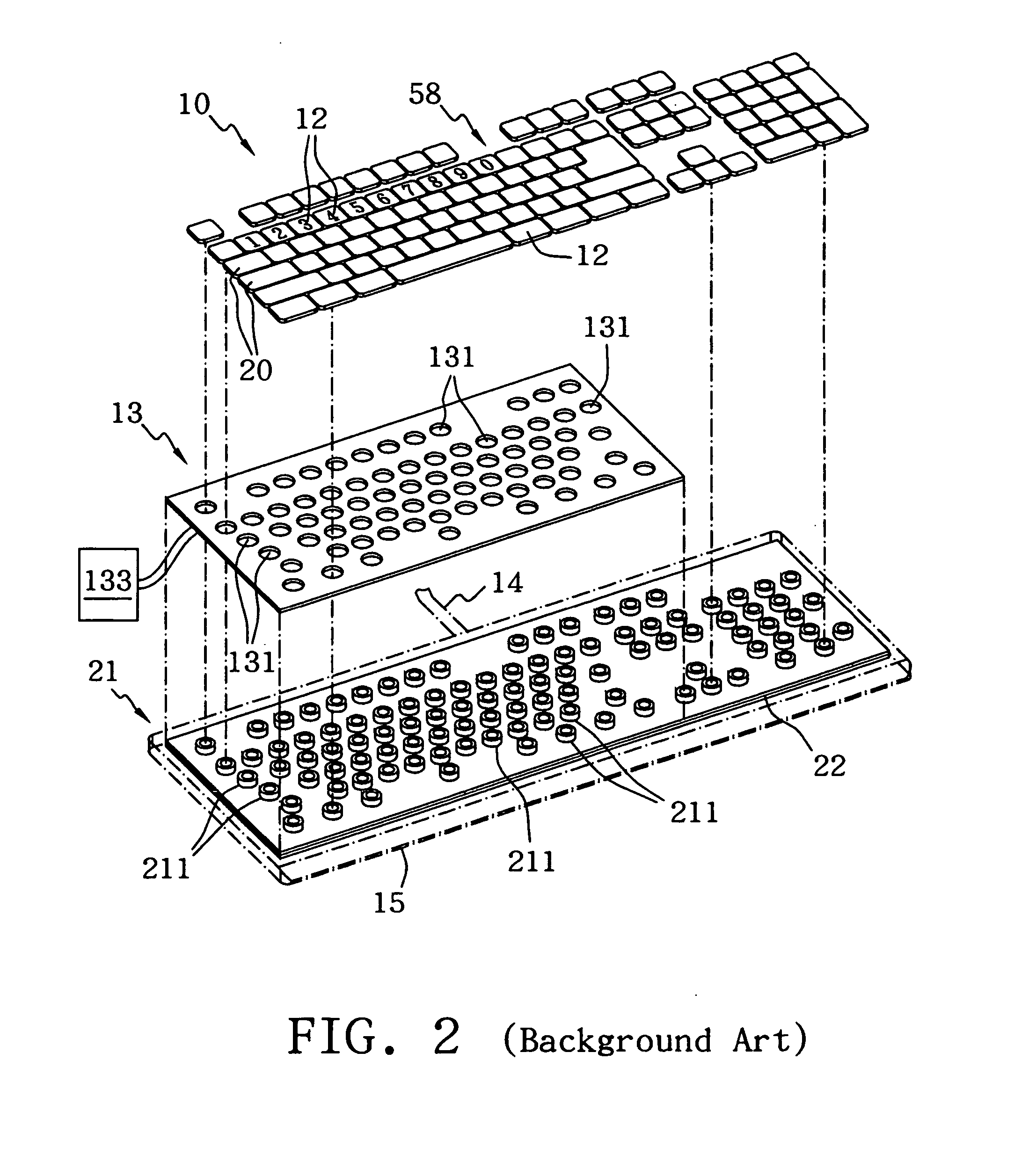
On the other hand, the deformed movement is still necessary for the key actuator 211, hence the total thickness of the key cap 12 is increased and the design of the keyboard structure becomes difficult.

Method used


Image

  • Illuminating membrane switch and illuminating keypad using the same
  • Illuminating membrane switch and illuminating keypad using the same
  • Illuminating membrane switch and illuminating keypad using the same

Examples


Embodiment Construction

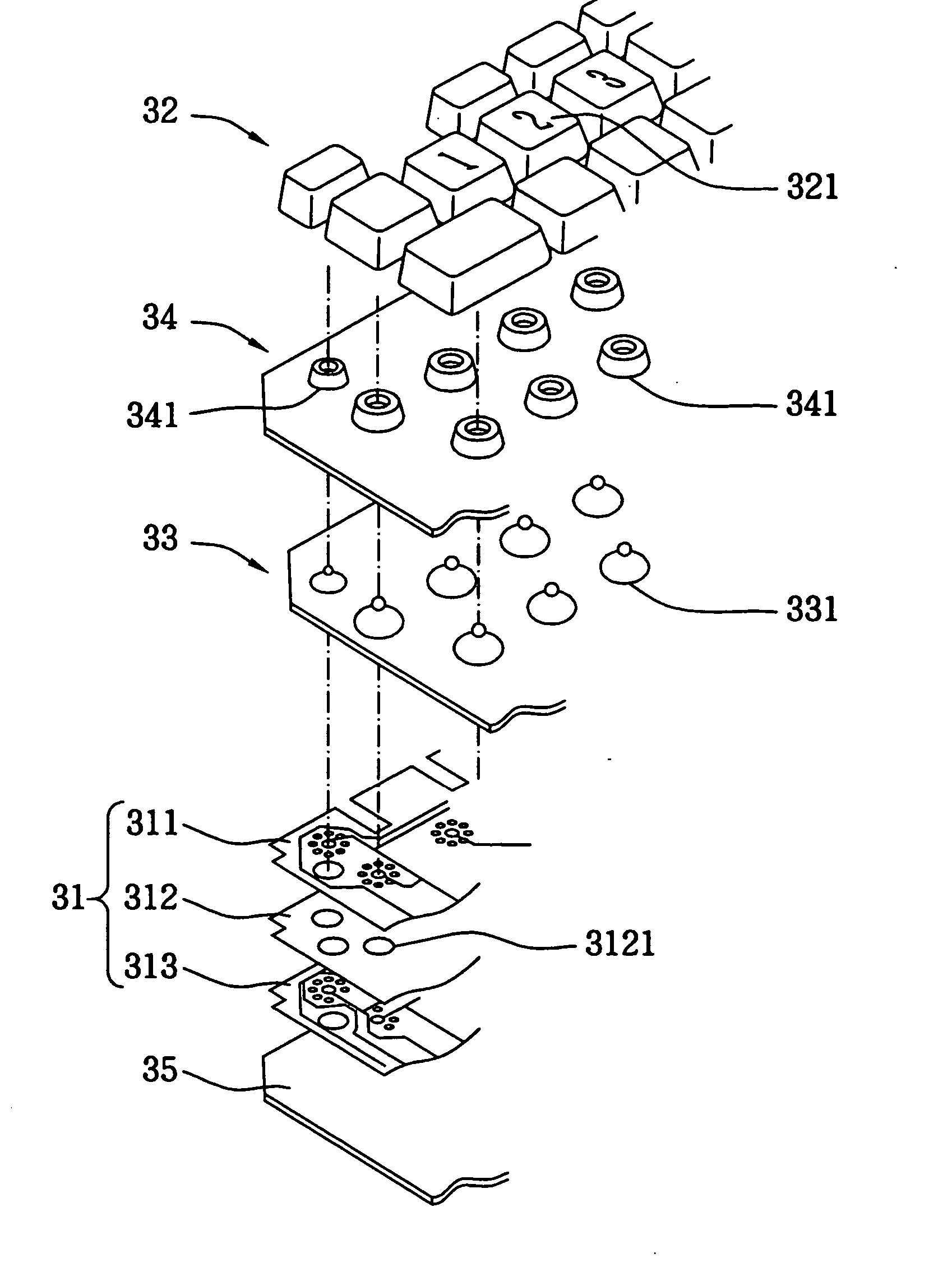
[0020]FIG. 3 is an exploded diagram of an illuminating key membrane and a keyboard or a keypad using the same in accordance with present invention. A plurality of key caps 32 are separately mounted on the seats 341 of an upper housing 34. Each of the key caps 32 is allowed to move down for a finite distance. Symbols are separately printed on the top surfaces of the key caps 32 to illustrate the functions or alphabet inputs of them. Moreover, an elastomer layer 33 made from silicone or rubber is placed under the seats 341, and has a plurality of key actuators 331 whose positions correspond to the positions of the key caps 32. Because the key actuator 331 is very flexible, it can rapidly return to its original shape after a keystroke is released.

[0021] When the key actuator 331 is deformed after the pressing of the key cap 32, an illuminating membrane switch 31 beneath it is switched on, and meanwhile an input signal corresponding to the key cap 32 is transmitted to a host through a ...


PUM


Abstract

An illuminating membrane switch includes an upper membrane sheet, an electroluminescent device and a lower membrane sheet. The electroluminescent device is interposed between the upper membrane sheet and lower membrane sheet on which switch circuits are printed. In addition to emitting rays through the upper membrane sheet, the electroluminescent device has a plurality of openings allowing the switch circuits of them to contact each other. The keyboard utilizes the illuminating membrane switch to detect any input of keystroke and light up the symbols on the surfaces of key caps for a user to identify the function or alphabetic input of each key cap.

Description

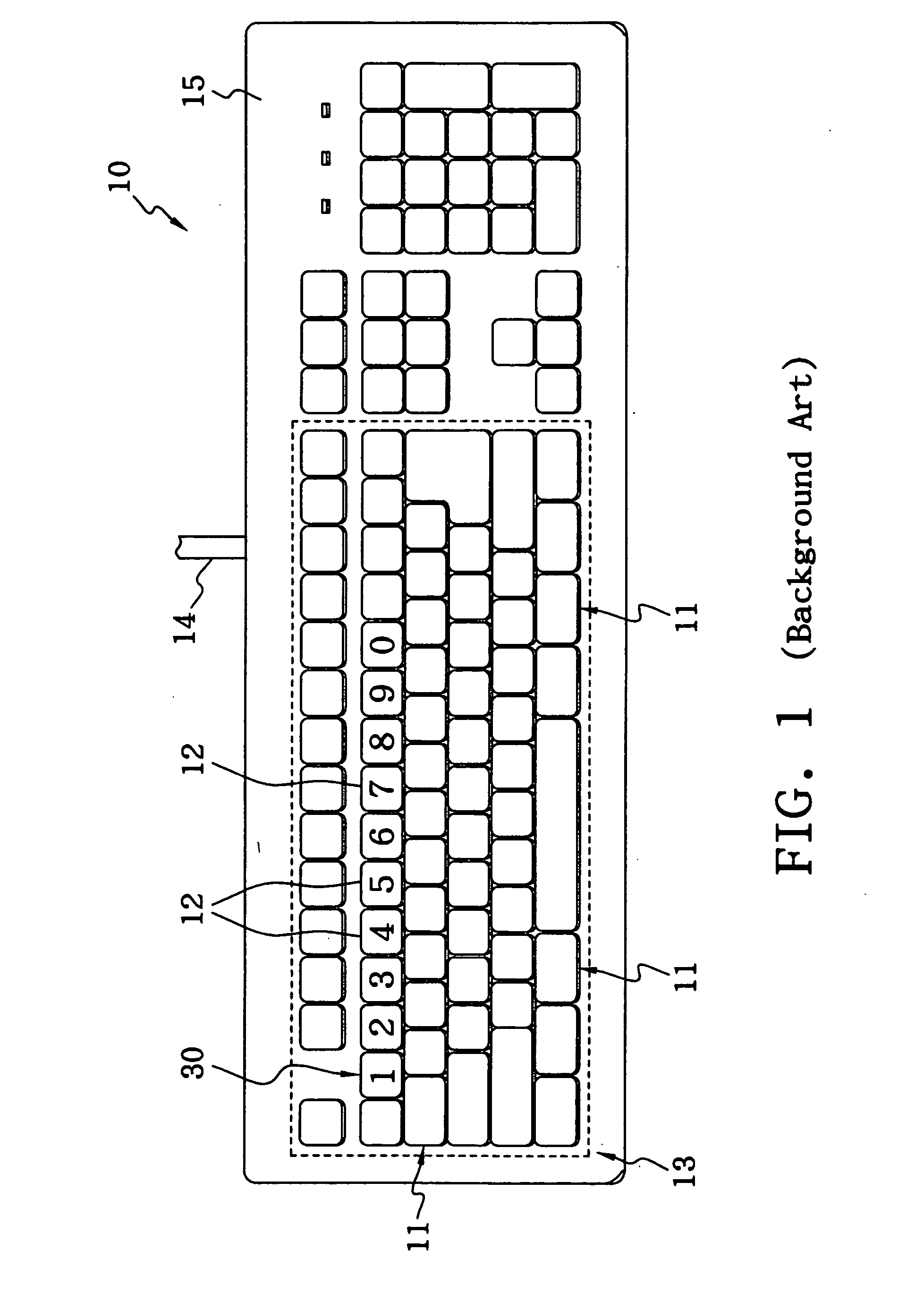
BACKGROUND OF THE INVENTION [0001] 1. Field of the Invention [0002] The present invention relates to an illuminating membrane switch and an illuminating keypad or keyboard using the same, more particularly to a membrane switch capable of emitting rays to highlight alphanumeric symbols on keys and detecting any keystroke. [0003] 2. Description of the Related Art [0004] When working in a condition with low light or even no light, a user cannot see the alphanumeric symbols on the keys of a keyboard clearly, for example, when a notebook computer is used on planes, or when a keyboard attached to equipment is used in a lithography laboratory. [0005]FIG. 1 is an upper view diagram of an illuminating keyboard disclosed is in U.S. Pat. No. 6,179,432. The keyboard 10 has a plurality of key caps 11 mounted on a housing 15 and is allowed to have finite downward displacement along its vertical direction. There is a symbol 12 printed on the surface of each of the key caps 11 to illustrate the fun...

Claims


Application Information

Patent Timeline
Patent Type & Authority Applications(United States)
IPC IPC(8): H01H9/00G06C7/02G06F3/02G06F3/023H01H3/12H01H9/18H01H13/702H01H13/83
CPCG06F3/0202H01H3/125H01H13/702H01H2233/036H01H2215/006H01H2219/018H01H2221/07H01H13/83
Inventor HUANG, HUEI-PINLIANG, CHIH-PING
Owner FIRST LITE CORP
Learn More