
Mounting apparatus for storage device

a technology for mounting apparatuses and storage devices, which is applied in the direction of electrical apparatus casings/cabinets/drawers, instruments, computing, etc., can solve the problems of storage devices being apt to be detached from the base and destroyed

Inactive Publication Date: 2006-12-14
HONG FU JIN PRECISION IND (SHENZHEN) CO LTD +1
View PDF24 Cites 16 Cited by
  • Summary
  • Abstract
  • Description
  • Claims
  • Application Information

AI Technical Summary

Benefits of technology

[0004] What is needed, therefore, is a mounting apparatus which is able to prevent inadvertent disengagement of a fixed storage device.

Problems solved by technology

However, the storage device is apt to be detached from the base and destroyed due to a careless operation of the operating member.

Method used


Image

  • Mounting apparatus for storage device
  • Mounting apparatus for storage device
  • Mounting apparatus for storage device

Examples


Embodiment Construction

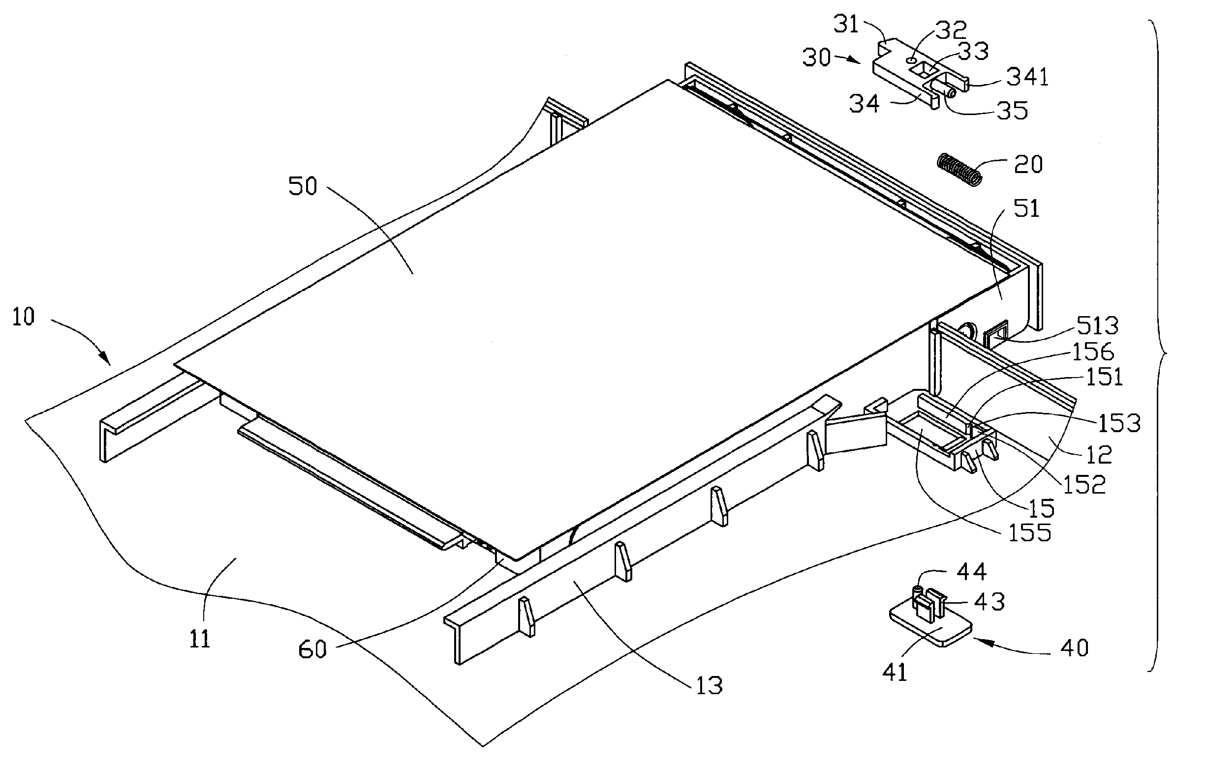
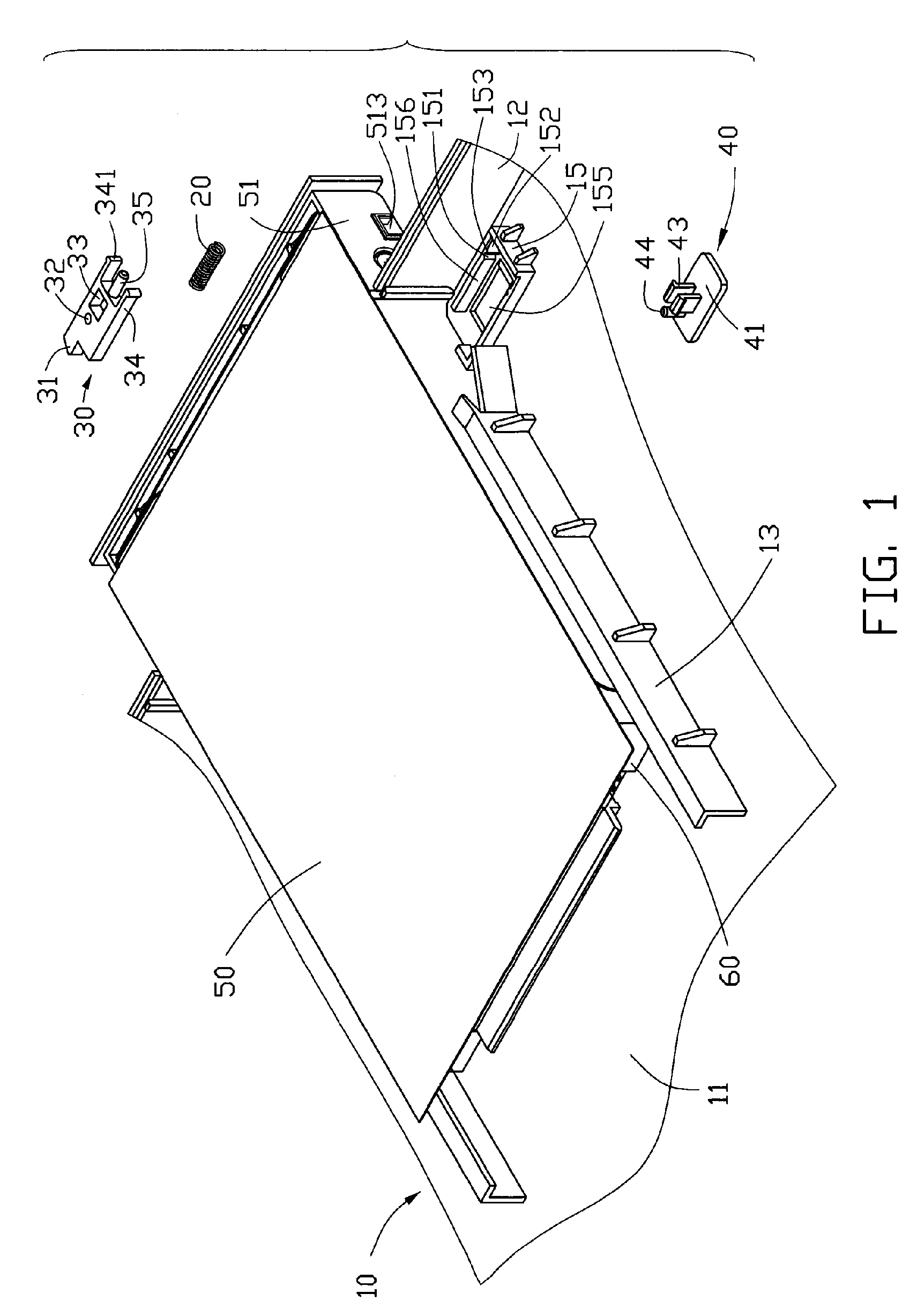
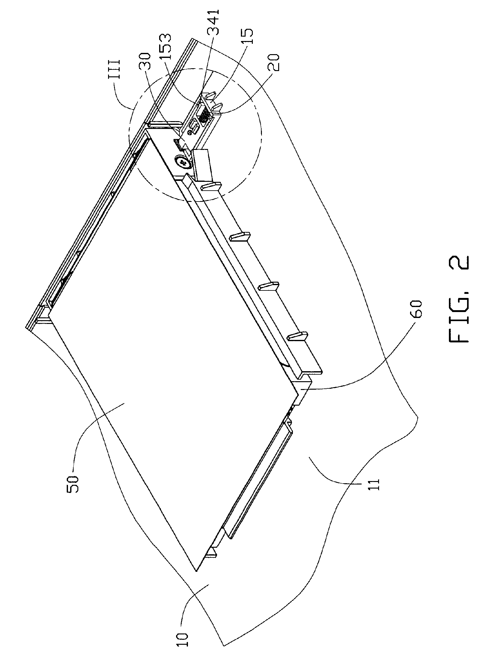
[0013] Referring to FIG. 1, a mounting apparatus for a storage device is provided in accordance with a preferred embodiment of the present invention. The mounting apparatus includes a base 10, an elastic member 20, a sliding member 30, an operating member 40 and a bracket 50 for fixing a storage device 60. In this embodiment, the storage device 60 is a hard disk drive.

[0014] The base 10 includes a bottom wall 11 and an end wall 12, two spaced sliding rails 13 are formed from the bottom wall 11 for mounting the bracket 50. A generally U-shaped fixing portion 15 is formed adjacent to the end wall 12. The fixing portion 15 includes two sidewalls 156. A hooking recess 151 and a sliding recess 152 are defined in each of the sidewalls 156, and a projection 153 is formed between the hooking recess 151 and the sliding recess 152. The sliding recess 152 is adjacent to an end of the fixing portion 15. A through hole 155 is defined through the bottom wall 11 of the fixing portion 15.

[0015] T...


PUM


Abstract

A mounting apparatus for a storage device includes a bracket for receiving the storage device and a base for mounting the bracket therein. A fixing portion including two sidewalls is formed on the base. A hooking recess is defined in one of the sidewalls of the fixing portion. A sliding member is received in the fixing portion for fixing the bracket, and the sliding member includes a hook to engage in the hooking recess of the fixing portion. An elastic member is received in the fixing portion for restoring the sliding member.

Description

CROSS-REFERENCES TO RELATED APPLICATION [0001] Relevant subject matter is disclosed in the copending U.S. patent application filed on the same date and having a same title with the present application, which is assigned to the same assignee with this patent application. FIELD OF THE INVENTION [0002] The present invention relates to a mounting apparatus, and more particularly to a mounting apparatus for a storage device. DESCRIPTION OF RELATED ART [0003] Typically, a storage device is fixed in a portable computer by a bracket, and a fixing mechanism is provided for fixing the bracket with the storage device. A mounting apparatus for a storage device is disclosed in Taiwan Patent No. 221956, which describes a mounting apparatus including a base, a sliding member with an inclined plane, an elastic member and an operating member engaging with the sliding member. The elastic member is connected to the sliding member for pushing the sliding member to insert into a slot of a storage device...

Claims


Application Information

Patent Timeline
IPC IPC(8): G06F1/16
CPCG06F1/183G11B33/12G06F1/187G06F1/184
Inventor SHI, ZHENGCHEN, ZHI-GANGLIN, KE-CHENGTSAI, CHIEN-LI
Owner HONG FU JIN PRECISION IND (SHENZHEN) CO LTD
Learn More