Method and apparatus for driving plasma display panel

a plasma display and plasma technology, applied in the direction of instruments, static indicating devices, etc., can solve the problems of increasing reducing the overall cost of the product, so as to improve the overall cost, simplify the driving circuit configuration, and reduce the cost

Inactive Publication Date: 2006-12-14
FORMOSA PLASMA DISPLAY CORP
View PDF1 Cites 4 Cited by
  • Summary
  • Abstract
  • Description
  • Claims
  • Application Information

AI Technical Summary

Benefits of technology

[0011] The primary object of the present invention is to provide a method and apparatus for driving plasma display panel (PDP) that effectively simplifies the driving circuit configuration of some electrodes without sacrificing display quality, hence helping to lower cost, increase profit and render the PDP more price competitive.
[0012] Another object of the present invention is to provide a method and apparatus for driving plasma display panel, characterized in which the potential of either the sustain electrode or scan electrode is kept at a constant voltage during the sustain discharge period and another electrode is used to generate differential potential required for alternate discharge so as to simplify the driving waveform generated by the electrode having constant potential.
[0013] In a preferred embodiment of the present invention, the plasma display panel comprises a plurality of discharge units composed by a plurality of address electrodes, sustain electrodes and scan electrodes. Its driving method is characterized by using a set of sustain electrode control signals and a set of scan electrode control signals to apply pulse signals of predefined voltage to respectively a plurality of sustain electrodes and a plurality of scan electrodes over a predefined period of time during a sustain discharge period, wherein by maintaining the potential of either the sustain electrodes or the scan electrode arranged in parallel at a constant level and driving another electrode to generate the differential voltage required for alternate discharge between the sustain electrodes and scan electrodes, the effect of continuous discharge and illumination is achieved. As such, the driving waveform generated by the electrode having constant potential and the configuration of sustain circuit for driving said electrode are simplified, which helps saves cost.

Problems solved by technology

Given that the pulsed voltage generating circuit 351 continuously and cyclically in a very short time at the same output end 354, it is unavoidable that the residual charge from the previous wave of output voltage would offset the emitted inverse voltage that follows, resulting in loss of energy.
It is apparent from the descriptions above that the addition of an energy recovery circuit 352 to improve the situation of energy offset between X electrode sub-circuit 35 and Y electrode sub-circuit 36 in the prior art complicates the circuit design and increase the overall cost of the product.

Method used


Image

  • Method and apparatus for driving plasma display panel
  • Method and apparatus for driving plasma display panel
  • Method and apparatus for driving plasma display panel

Examples


Embodiment Construction

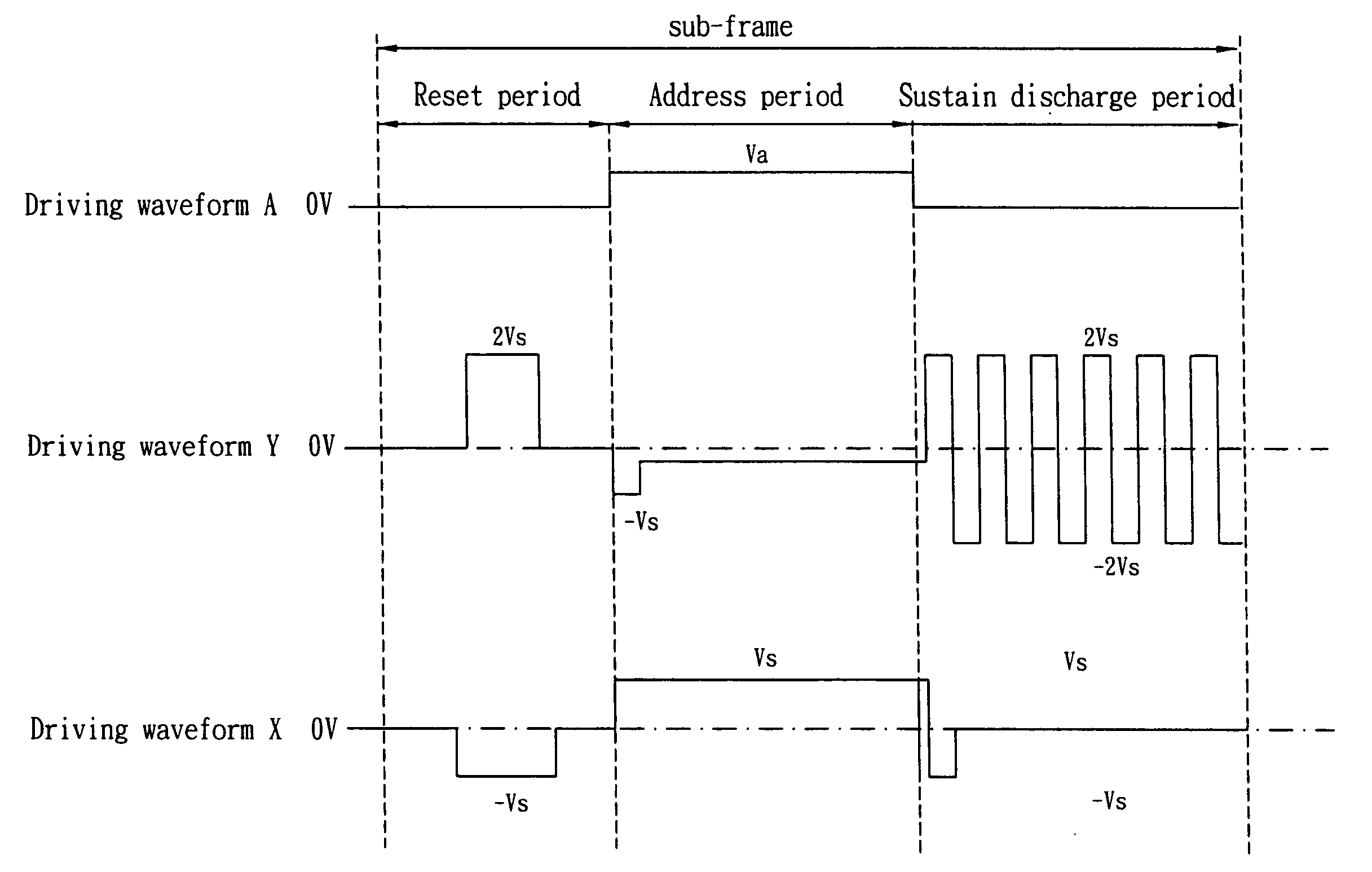
[0022] Referring to FIG. 3 and FIG. 4 which illustrate the first preferred embodiment of the method and apparatus for plasma display panel according to the invention, FIG. 3 shows the driving apparatus 40 in the first preferred embodiment of the plasma display panel. FIG. 4 shows the time-series driving waveforms in the first preferred embodiment.

[0023] As shown in FIG. 3, the plasma display panel in this embodiment consists of a plurality of address electrodes arranged at a predefined space apart (A1, A2, . . . Am), a plurality of sustain electrodes arranged at a predefined space apart (X1, X2, X3 . . . Xn), and a plurality of scan electrodes arranged at a predefined space apart (Y1, Y2, Y3, . . . Yn). Each sustain electrode (X1, X2, X3 . . . Xn) and scan electrode (Y1, Y2, Y3, . . . Yn) are alternately arrayed in parallel to each other and intersect respectively with address electrode (A1, A2, . . . Am) in the direction of projection to constitute a plurality of discharge units (...


PUM


Abstract

A method for driving plasma display panel is disclosed. The plasma display panel comprises a plurality of discharge units composed by a plurality of address electrodes, sustain electrodes and scan electrodes. Its driving method is characterized by using a set of sustain electrode control signals and a set of scan electrode control signals to apply pulse signals of predefined voltage to respectively a plurality of sustain electrodes and a plurality of scan electrodes over a predefined period of time during the sustain discharge period to enable them to alternately discharge and emit light, wherein during the sustain discharge period, either the scan electrode (Y electrode) or the sustain electrode (X electrode) is maintained at a constant potential and another electrode is used to generate the differential voltage required for alternate discharge between the sustain electrodes and scan electrodes to achieve the effect of continuous discharge and illumination. As such, the circuit design for the electrode having a constant potential may be greatly simplified, thereby offering the advantages of simplifying the driving waveform and lowering the circuit cost.

Description

BACKGROUND OF INVENTION [0001] 1. Field of the Invention [0002] The present invention relates to a method for driving plasma display panel, in particular, a method for achieving the functions of simplifying the driving waveform and lowering the circuit cost by maintaining the potential of either the scan electrode (Y electrode) or sustain electrode (X electrode) of the plasma display panel at a constant level and using another electrode to generate differential voltage required for the alternate discharge between sustain electrode and scan electrode within a sustain discharge period. [0003] 2. Description of the Prior Art [0004]FIG. 1A and FIG. 1B are respectively a schematic view and a cross-sectional view of a conventional AC plasma display panel 1 (referring as PDP hereinafter). The PDP 1 has an upper substrate 11 and a lower substrate 12. The inner side of upper substrate 11 is configured in sequence with a plurality of parallel transparent electrodes 111, a plurality of bus ele...

Claims


Application Information

Patent Timeline
Patent Type & Authority Applications(United States)
IPC IPC(8): G09G3/28
CPCG09G3/294G09G2310/06G09G3/296
Inventor TSAI, YU TSUNGLIU, NAN CHUNCHIEN, MENG HUNG
Owner FORMOSA PLASMA DISPLAY CORP
Why Eureka
Try Eureka