
Optimized energy management system

a technology of energy management system and energy supply, applied in the field of energy management, can solve the problems of limited use of alternative sources and technologies, difficulty in integrating such sources and devices into conventional electrical systems, and limited success

Active Publication Date: 2006-12-07
GRIDPOINT
View PDF99 Cites 855 Cited by
  • Summary
  • Abstract
  • Description
  • Claims
  • Application Information

AI Technical Summary

Benefits of technology

[0007] In another variation, when the algorithm determines that electricity can be favorably sold to the electricity grid, alternative energy sources and storage devices are activated and electricity is sold to the grid. Customer preferences for maintaining

Problems solved by technology

However, the use of such alternative sources and technologies has been limited because of such factors as difficulty in recovering costs; unpredictability of alternative energy supplies (e.g., sun, wind), and difficulty in integrating such sources and devices into conventional electrical systems.
However, such arrangements are typically ad-hoc and require that customers submit to the whims of the utility company.
Such programs have met with limited success for various reasons most particularly the inability of some types of energy users to curtail energy use and the lack of real-time information regarding the immediate cost of energy usage.

Method used


Image

  • Optimized energy management system
  • Optimized energy management system
  • Optimized energy management system

Examples


Embodiment Construction

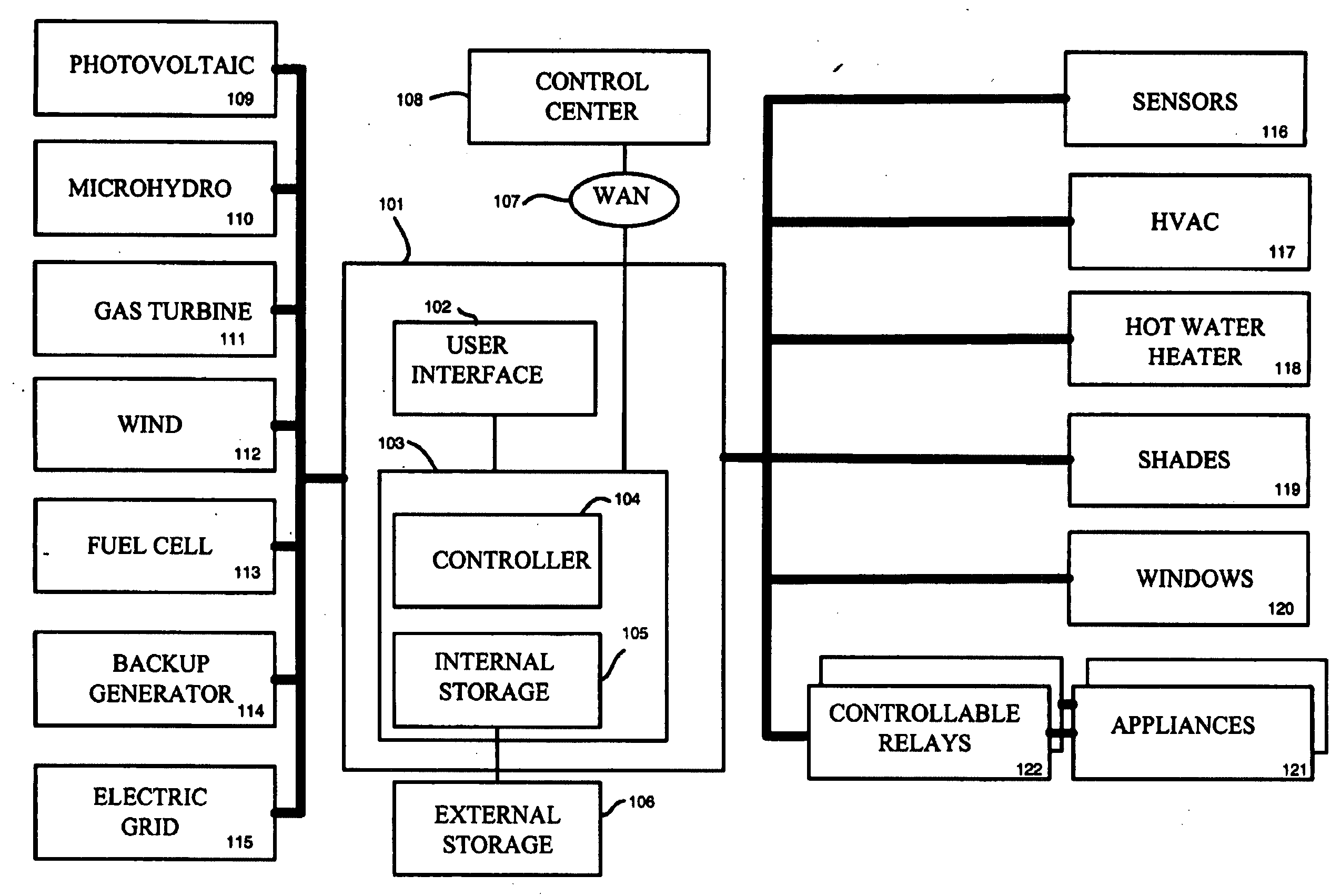
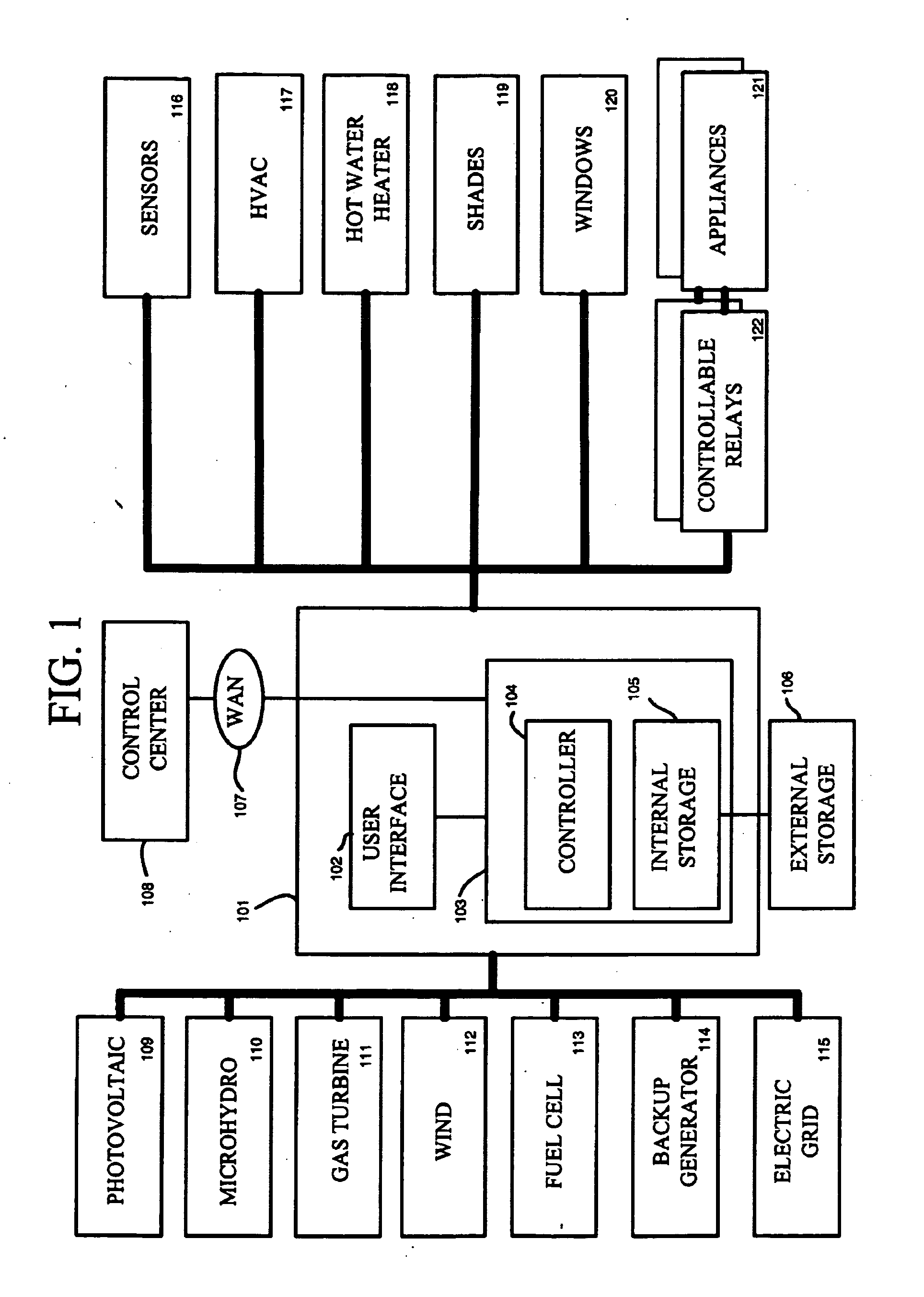
[0024]FIG. 1 shows a system employing various principles of the present invention. As shown in FIG. 1, apparatus 101 includes a unit 103 comprising a controller 104 and an internal storage device 105. Internal storage device 105 may comprise, for example, a plurality of lead-acid or nickel-metal-hydride storage batteries for storing electrical energy, and / or large capacitors. External storage device 106 may be optionally included to store additional electrical energy. As explained in more detail herein, storage devices 105 and 106 may provide power to various devices during times of electrical grid outages or during periods where electrical grid costs exceed certain thresholds, and they may be used to sell power back to the electrical utility during times that are determined to be favorable. The storage capacities of devices 105 and 106 may be selected to suit a particular environment, such as the needs of a typical home residence, business, or other electrical consumer. The smalles...


PUM


Abstract

Methods and systems are provided for optimizing the control of energy supply and demand. An energy control unit includes one or more algorithms for scheduling the control of energy consumption devices on the basis of variables relating to forecast energy supply and demand. Devices for which energy consumption can be scheduled or deferred are activated during periods of cheapest energy usage. Battery storage and alternative energy sources (e.g., photovoltaic cells) are activated to sell energy to the power grid during periods that are determined to correspond to favorable cost conditions.

Description

FIELD OF THE INVENTION [0001] The invention relates generally to the field of energy management, and more particularly, to various systems and methods for optimizing the control of energy supply and demand in residences and businesses. BACKGROUND OF THE INVENTION [0002] As energy demand around the world has increased, pressure from environmental concerns and energy price volatility has heightened the need for energy conservation and alternative energy sources. Programmable thermostats have permitted consumers to program their heating and cooling systems to reduce consumption during periods when they are not home or are asleep. Solar panels, fuel cells, windmills, back-up generators and other energy sources have become increasingly available for use in residential homes and businesses. However, the use of such alternative sources and technologies has been limited because of such factors as difficulty in recovering costs; unpredictability of alternative energy supplies (e.g., sun, win...

Claims


Application Information

Patent Timeline
IPC IPC(8): H02J3/00G06Q50/00
CPCG06Q50/06H02J3/14H02J3/32H02J7/34Y04S10/54Y02E10/566Y02E70/30Y04S20/222Y02B70/3225H02J3/008Y04S50/10H02J2310/64Y02E10/56G05B15/02H02J3/00
Inventor MILLER, CRAIG HOWARD
Owner GRIDPOINT
Learn More