
Vision system and a method for scanning a traveling surface to detect surface defects thereof

Active Publication Date: 2006-12-07
INSTITUT NATIONAL D'OPTIQUE
View PDF10 Cites 47 Cited by
  • Summary
  • Abstract
  • Description
  • Claims
  • Application Information

AI Technical Summary

Problems solved by technology

Traveling surfaces such as roads, carriageways and the like are inherently subject to heavy wear from traffic and degradation from weather conditions and ground movements.
It is known that wear of the roads foundations typically begins with the cracking of the pavement.
At the present such procedures for obtaining this information are very time consuming and labor intensive and are inherently inaccurate and unreliable.
However, most existing imaging systems, which use 2D cameras, often suffer from non-uniform lighting and shadows generally caused by the presence of the sun, trees, viaducts, buildings, the inspection vehicle itself or other vehicles as non-limitative examples.
With these systems, detection of cracks is neither accurate nor reliable due to the limited resolution of the cameras and the poor contrast of the gathered images.
Moreover, because of the presence of the sun, it is challenging task to maintain image quality under this highly variable and uncontrolled light.
However, both sets of images may suffer from other shadows coming from surrounding trees, buildings for example.
Moreover, this system is quite cumbersome since it relies on the use of a set of camera both in front and rear of the vehicle.
This system is mounted on the rear of a vehicle and is quite cumbersome.
Moreover, this system has to operate at night-time to avoid shadows and difficult illumination conditions caused by the sun.
One major disadvantage of such a configuration is that the angle between the strobe lights and the cameras are a cause a major non-uniformities in the images.
This is caused by the fact that the pavement areas that are closer to the strobe lights appear much brighter than those further away, a lighting gradiant is thus created and reduces the quality of the images and contrasts.
The major disadvantage of this system is the large quantity of electricity needed, thousands of watts, to power the system.
The whole system is thus cumbersome, and, moreover, it is not able to provide good shadow contrast in the images especially as pertains to longitudinal cracks.
None of the above mentioned inspection systems is adapted to perform a fast enough automatic accurate road inspection immune to surrounding light condition changes while providing a compact and power efficient assembly.

Method used


Image

  • Vision system and a method for scanning a traveling surface to detect surface defects thereof
  • Vision system and a method for scanning a traveling surface to detect surface defects thereof
  • Vision system and a method for scanning a traveling surface to detect surface defects thereof

Examples


Embodiment Construction

[0032] In the following description, similar features in the drawings have been given similar reference numerals and, in order to weight down the figures, some elements are not referred to in some figures if they were already identified in a precedent figure.

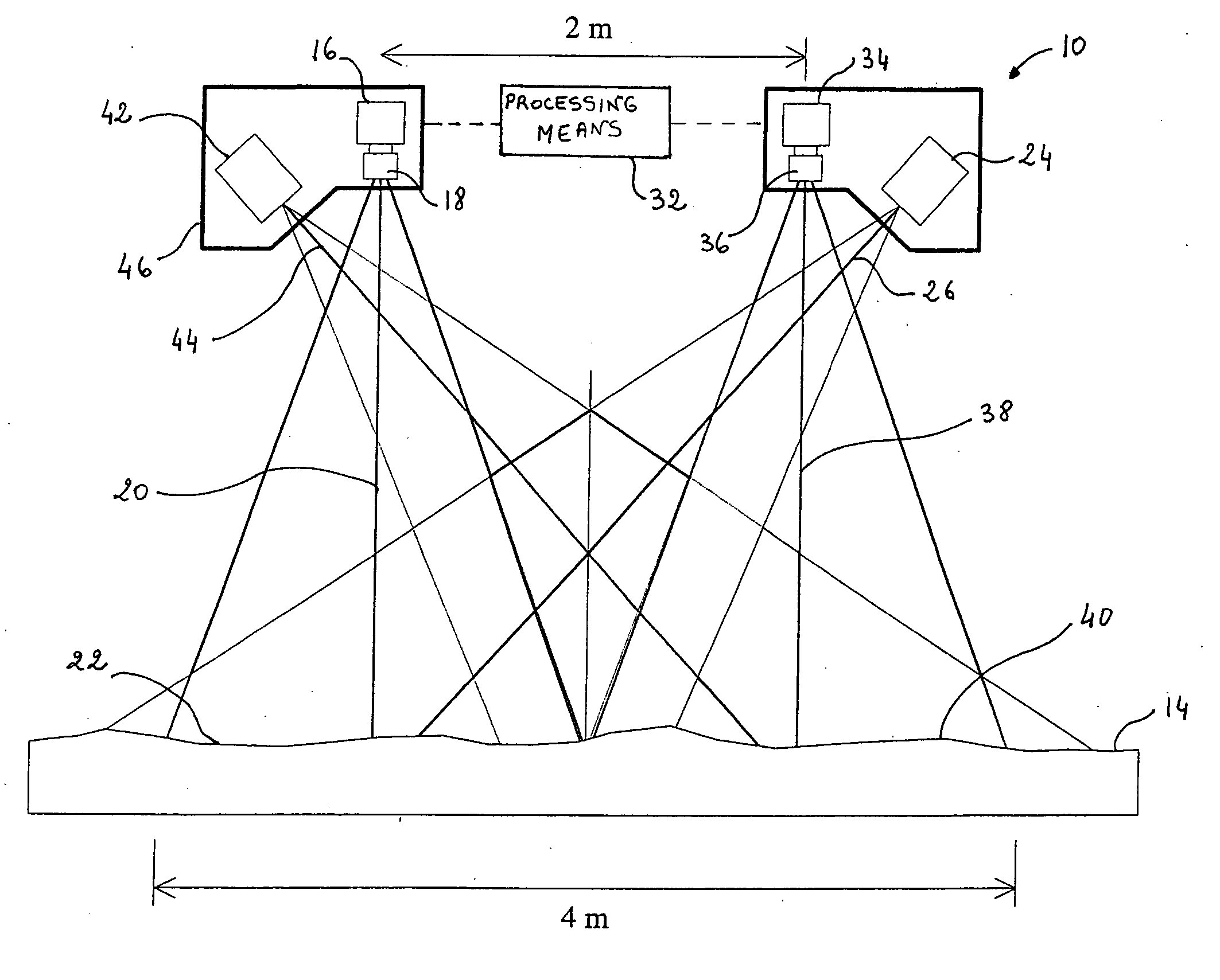
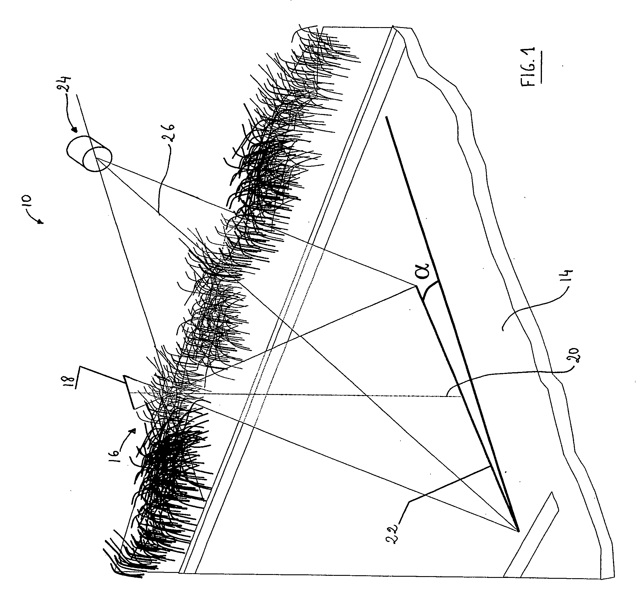
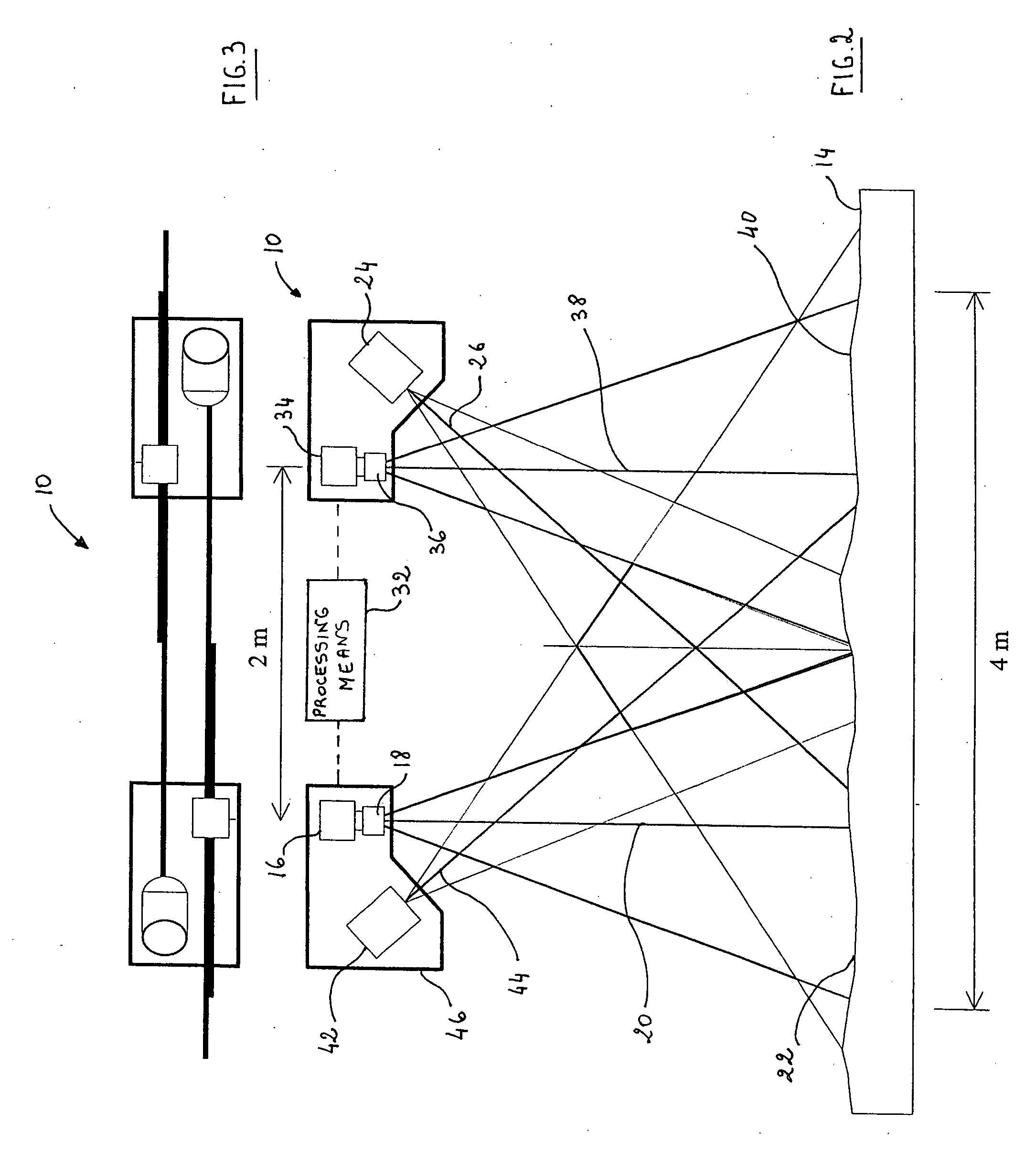
[0033] The present invention concerns a vision system which is mountable on a vehicle, such a van or a trailor for example, traveling onto a traveling surface such a road as a non-limitative example for scanning the traveling surface to detect surface defects thereof. The vision system, which can also be referred to as a pavement inspection apparatus, is capable of providing very reliable and accurate information on the road conditions, specially concerning the longitudinal and transversal profile of the pavement. Indeed, the vision system of the present invention is particularly devised to be immune to surrounding light condition variations, thereby allowing to provide optimum cracks image contrast for both transverse and long...


PUM


Abstract

There is provided a vision system and a method for scanning a traveling surface such a road to detect surface defects thereof such as cracks. The vision system, which is mountable on a vehicle, is provided with a linear imaging system for imaging successive adjacent transversal linear portions of the traveling surface as the vehicle advances. The vision system is also provided with laser line projecting means angularly projecting a laser line onto the transversal linear portion of the traveling surface to be imaged in a substantially coplanar relationship with the linear imaging system. The present vision system is particularly devised to be immune to surrounding light conditions variations to provide optimum cracks image contrast for both transverse and longitudinal cracks.

Description

FIELD OF THE INVENTION [0001] The present invention generally relates to road visual inspection, and more particularly concerns a vision system and a method for scanning a traveling surface such as a road to detect surface defects thereof. BACKGROUND OF THE INVENTION [0002] Traveling surfaces such as roads, carriageways and the like are inherently subject to heavy wear from traffic and degradation from weather conditions and ground movements. It is known that wear of the roads foundations typically begins with the cracking of the pavement. This necessitates regular monitoring of the pavement condition to plan maintenance programs. [0003] Fundamental to an effective maintenance and reconstruction program is the acquisition of accurate information concerning the condition of the pavement. At the present such procedures for obtaining this information are very time consuming and labor intensive and are inherently inaccurate and unreliable. [0004] Despite a number of attempts that have b...

Claims


Application Information

Patent Timeline
IPC IPC(8): G06K9/00
CPCG01C7/04G01N21/8901G01N21/8806
Inventor LAURENT, JOHNDOUCET, MICHEL
Owner INSTITUT NATIONAL D'OPTIQUE
Learn More