Cable connector for balanced transmission

a technology of balanced transmission and cable connector, which is applied in the direction of coupling contact members, coupling device connections, coupling protective earth/shielding arrangements, etc., can solve the problems of poor influence on transmission characteristics, high signal speed in clients and servers, and difficult to provide excellent shielding, etc., to achieve the effect of improving the transmission characteristics of high speed signals

Inactive Publication Date: 2006-11-30
FUJITSU COMPONENENT LTD
View PDF5 Cites 26 Cited by
  • Summary
  • Abstract
  • Description
  • Claims
  • Application Information

AI Technical Summary

Benefits of technology

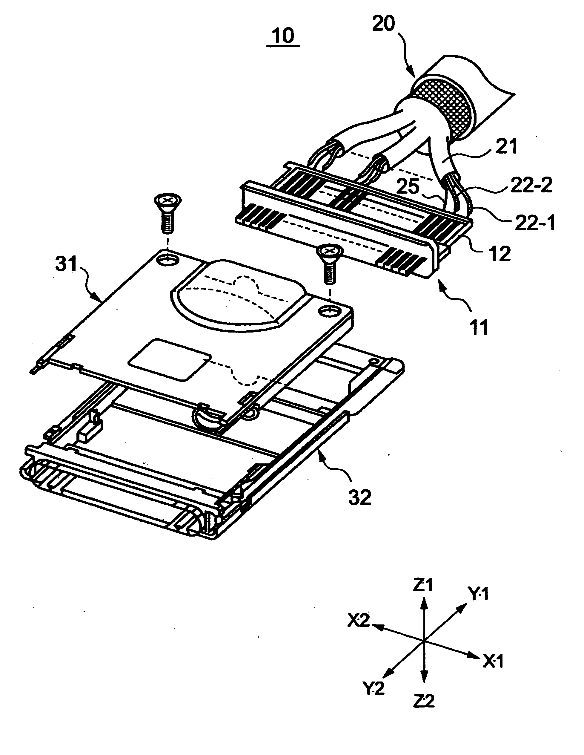
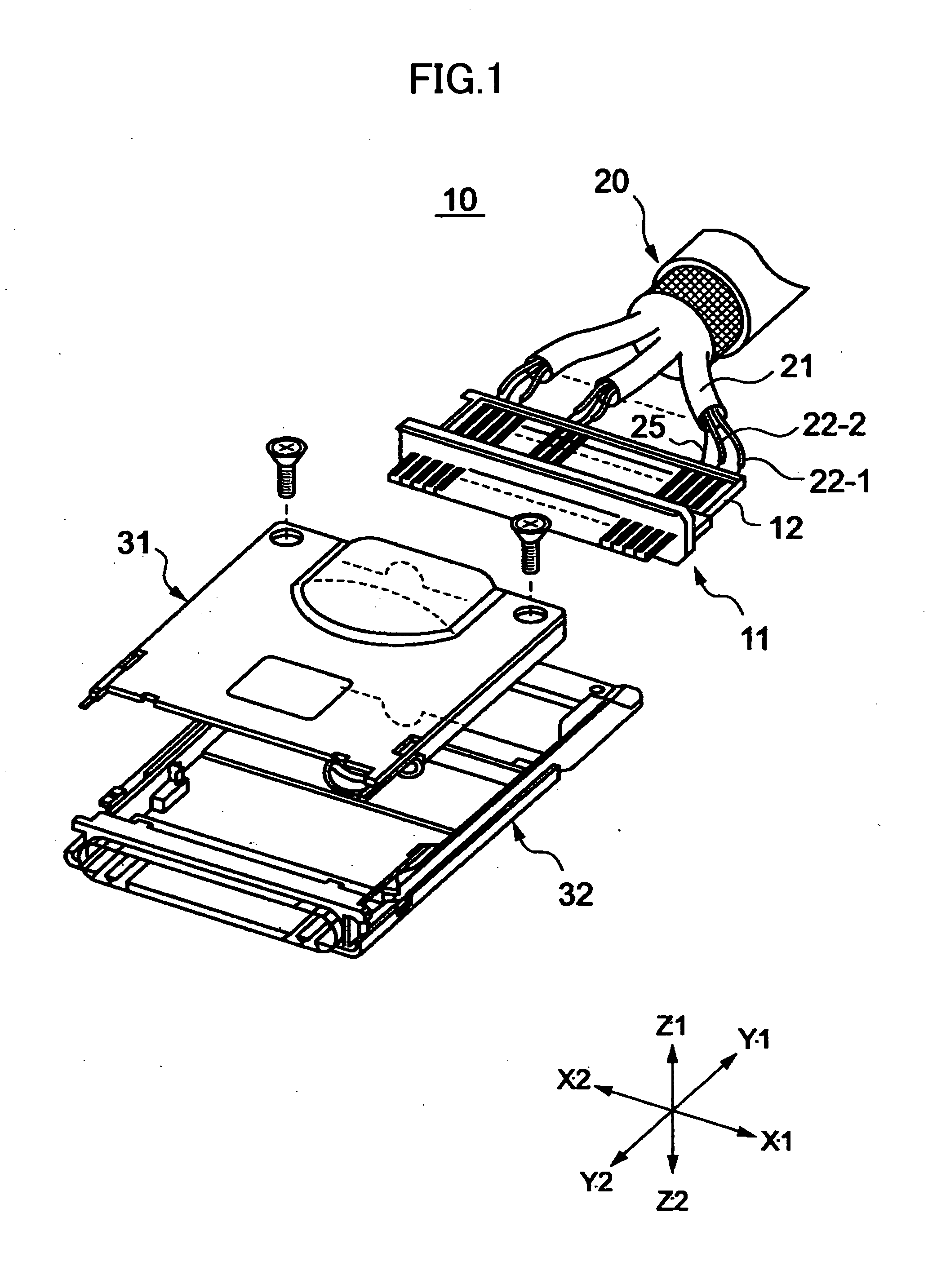
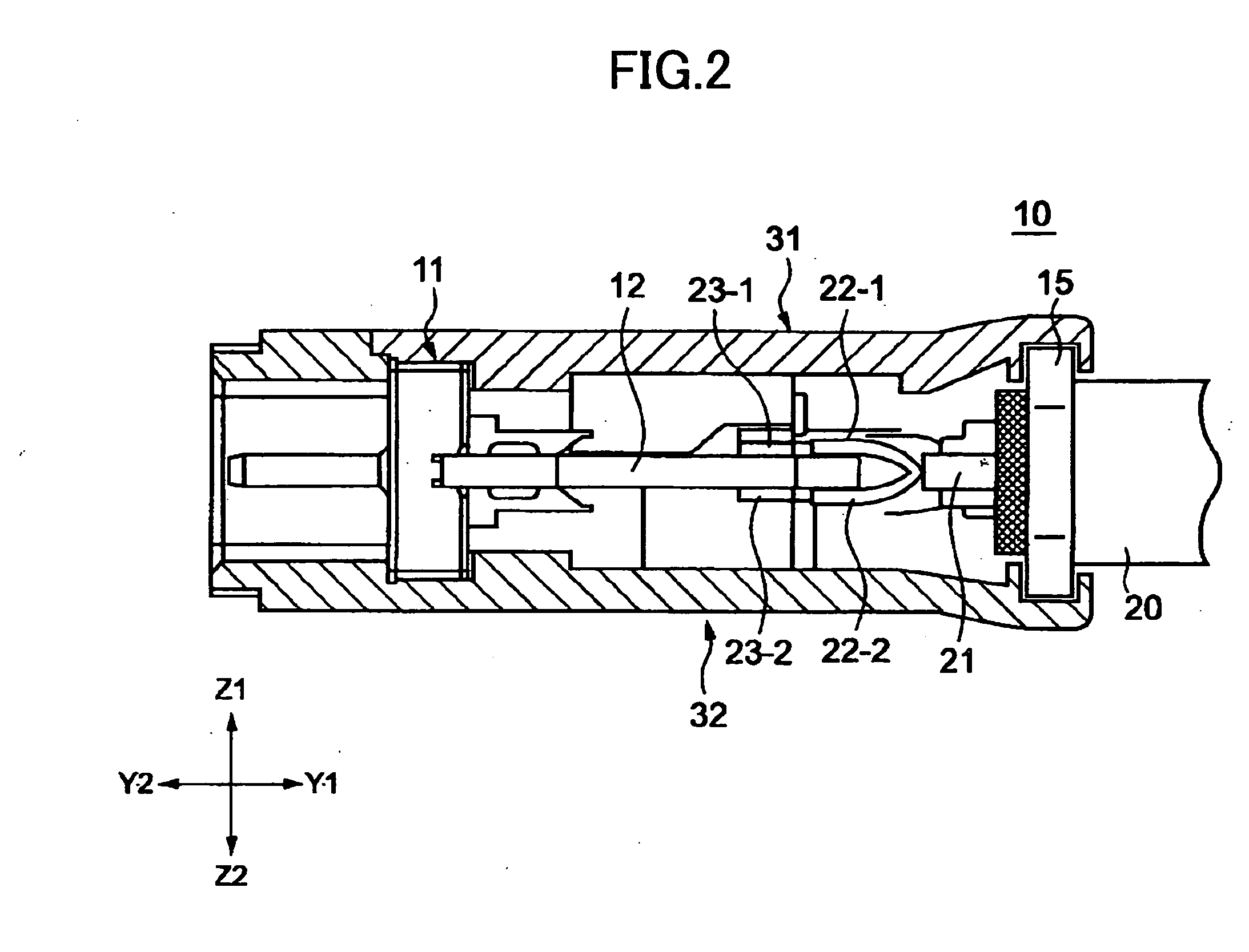
[0012] Accordingly, the present invention may provide a cable connector for balanced transmission in which transmission characteristics of high speed signals are improved.
[0014] According to embodiments of the present invention, the positions of the first and second signal wire connecting parts and the drain wire connecting part can be easily decided by the spacer member.
[0015] In addition, according to the embodiments of the present invention, the first and second signal wires of the cable for balanced transmission are respectively connected to the first and second signal wire connecting parts whose positions are decided, and the drain wire of the cable for balanced transmission is connected to the drain wire connecting part whose position is decided. Therefore, connecting wires can be executed in a stable manner without deforming the first and second signal wire connecting parts and the drain wire connecting part. Consequently, the manufacturing efficiency becomes high.
[0016] In addition, the first and second signal wires are directly connected to the first and second signal contact members, respectively, without being connected via a relay board. Therefore, the crosstalk characteristic of the cable connector for balanced transmission of an embodiment of the present invention is improved.
[0017] In addition, the ground contact members sandwich the first and second signal contact members therebetween and shield them. Consequently, the shielding effect for the first and second signal wires is improved.

Problems solved by technology

Consequently, it is difficult to provide excellent shielding at the place between adjacent wiring patterns in the X1-X2 direction comparable to the shielding degree at the contact assembly body 11.
Recently, the signal speeds in clients and servers have become high; therefore, a bad influence on transmission characteristics caused by poor shielding at the relay board 12 cannot be ignored.

Method used


Image

  • Cable connector for balanced transmission
  • Cable connector for balanced transmission
  • Cable connector for balanced transmission

Examples


first embodiment

[0054]FIG. 4 is an exploded perspective view of a cable connector for balanced transmission 50 according to a first embodiment of the present invention. FIG. 5A is a perspective view showing tips of a cable for balanced transmission 20 that are connected to a contact assembly body 51 in the cable connector for balanced transmission 50. FIG. 5B is a diagram showing details of the connection shown in FIG. 5A. FIG. 6 is an exploded perspective view in which the tips of the cable for balanced transmission 20 and the contact assembly body 51 are shown. FIG. 7 is a cross-sectional view of the cable connector for balanced transmission 50 at a position of first and second signal contact members 53 and 54. FIG. 8 is a cross-sectional view of the cable connector for balanced transmission 50 at a position of a ground contact member 55. FIG. 9 is a cross-sectional view of the cable connector for balanced transmission 50 at a position of a locking arm member 56. FIG. 10 is a transverse sectional...

second embodiment

[0100]FIG. 19 is a perspective view of a cable connector for balanced transmission 50A according to a second embodiment of the present invention. The cable connector for balanced transmission 50A includes an outer cover 110A and a hood 100A which are formed by potting a resin and an operating section 111A reinforced by a reinforcing plate member 200.

[0101] The cable connector for balanced transmission 50A is manufactured by the following processes. In FIG. 19, (a), (b), and (c) show the processes.

[0102] First, a cable connector main body 190A is assembled by surrounding the contact assembly body 51 (not shown) and the spacer member 60 (not shown) with the use of the shielding cover assembly body 80 and further by clamping the end of the cable for balanced transmission 20 with the ring part 85. These processes are the same as those in the first embodiment.

[0103] Next, as shown in FIG. 19(a), a reinforcing plate member 200 covers the protrusions 56d and 57d of the locking arm membe...

third embodiment

[0106]FIG. 20 is a perspective view of a cable connector for balanced transmission 50B according to a third embodiment of the present invention. The cable connector for balanced transmission 50B includes an outer cover 110B and a hood 100B which are formed by outsert molding and an operating section 301 formed by an operating section member 300. FIG. 21 is a cross-sectional view of a part of the cable connector for balanced transmission 50B shown in FIG. 20.

[0107] The cable connector for balanced transmission 50B is manufacture by the following processes. In FIG. 20, (a), (b), and (c) show the processes.

[0108] As shown in FIG. 20(a), the operating section member 300 is a plate-shaped member and includes the operating section 301 at the Y1 side and two openings 302 and 303 at the Y2 side. In addition, a shielding cover assembly body 80B includes two protrusions 312 and 313 in the upper face. The height “a” of the protrusions 312 and 313 is less than the thickness “t” of the operati...


PUM


Abstract

A cable connector for balanced transmission is disclosed. A spacer member is attached to a contact assembly body in the cable connector for balanced transmission, a first signal wire connecting part of a first signal contact member is inserted into a first groove of the spacer member, a second signal wire connecting part of a second signal contact member is inserted into a second groove of the spacer member, and a ground contact member is inserted in a slit of the spacer member, so that their positions are decided. A cable for balanced transmission includes plural pairs of wires, and a first signal wire of the pair of wires is soldered to the first signal connecting part, a second signal wire thereof is soldered to the second signal connecting part, and a drain wire thereof is soldered to a drain wire connecting part of the ground contact member.

Description

BACKGROUND OF THE INVENTION [0001] 1. Field of the Invention [0002] The present invention generally relates to a cable connector for balanced transmission in which a number of pairs of wires are used. [0003] 2. Description of the Related Art [0004] As data transmission systems, there are systems such as a normal transmission system that uses a wire for each data signal, and a balanced transmission system that uses a pair of wires for each data signal and transmits a + signal and a − signal, whose size is the same as that of the + signal with the opposite direction from the + signal, at the same time. The balanced transmission system has an advantage of being relatively immune to noise compared with the normal transmission system. Therefore, the balanced transmission system has been widely used. In order to establish a transmission line that executes balanced transmission of data between apparatuses, a cable connector for balanced transmission is used. The cable connector for balance...

Claims


Application Information

Patent Timeline
IPC IPC(8): H01R12/24
CPCH01R4/023H01R13/24H01R13/506H01R13/5213H01R13/5216H01R13/5804H01R13/6275H01R13/6658H01R13/6582H01R13/6585H01R13/6593H01R12/716H01R13/65912
Inventor MORIYAMA, SATOSHIKONDOU, TAKAHIROSATO, KIYOSHIKOBAYASHI, MITSURU
Owner FUJITSU COMPONENENT LTD
Why Eureka
Try Eureka