Eureka AIR delivers breakthrough ideas for toughest innovation challenges, trusted by R&D personnel around the world.

Lightweight safety support for tires

a safety support and lightweight technology, applied in the field of safety supports, can solve the problems of limiting the design possibilities of these supports, destroying tires fast immediately, and limiting the optimization of this structure, so as to reduce the flexural stiffness of the support, facilitate the mounting and dismounting of the tire/support/wheel mounted assembly, and limit the flexural stiffness of the crown

Inactive Publication Date: 2006-11-23
MICHELIN RECH & TECH SA
View PDF10 Cites 4 Cited by
  • Summary
  • Abstract
  • Description
  • Claims
  • Application Information

AI Technical Summary

Benefits of technology

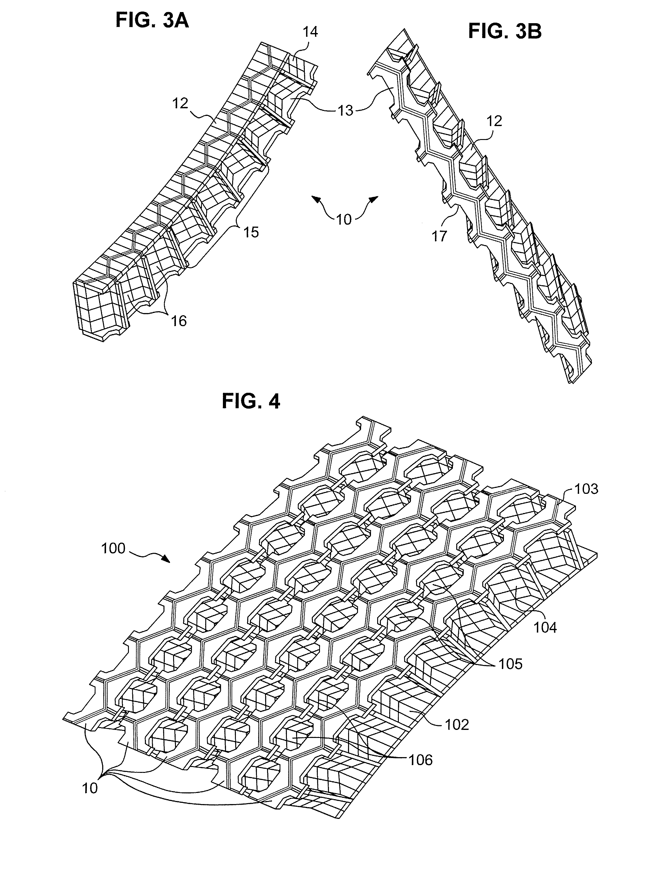
[0014] The axial assembly of the annular sections makes it possible to obtain, at the level of the annular body of the support, connecting zones between adjacent sections of constant, well-controlled thickness, because assembly takes place by butt-joining the axial ends of the connecting walls.
[0022] By way of example, such partitions may comprise radial partitions inclined axially to constitute, after assembly supporting elements of the annular body of the support in the form of chevrons. One of the advantages of a geometry of this type is to reduce very significantly the flexural rigidity of the whole of the support compared with a support which comprises circumferentially continuous supporting elements. This facilitates the operations of mounting the supports and, in particular, their introduction into the torus of the tire, which constitutes the first step of these assembly operations.
[0025] This crown may also be circumferentially discontinuous. As in the case of the supporting elements in the form of chevrons, a discontinuous crown even more substantially reduces the flexural stiffness of the support, which facilitates the mounting and the dismounting of the tire / support / wheel mounted assembly.
[0026] The annular sections may comprise connecting walls which comprise radially the crown of the section. This makes it possible to have a support assembled with an axially continuous crown. The connecting walls may also extend radially to the level of the crown.
[0035] The supports according to the invention may comprise 2 to 14 annular sections. The assembly of two annular sections already provides very significant freedom in designing the support, and when the number is close to 14, each section has an axial width of the order of 10 mm, thus being an object which is very easy to produce by injection.

Problems solved by technology

Without the presence of such supports, the rim will almost immediately destroy the tire if travel is continued.
This constraint restricts the design possibilities for these supports.
The result is that these walls of the cells have a thickness which is systematically doubled in the gluing zones and constant in the rest of the structure, which limits optimization of this structure.

Method used


Image

  • Lightweight safety support for tires
  • Lightweight safety support for tires
  • Lightweight safety support for tires

Examples


Embodiment Construction

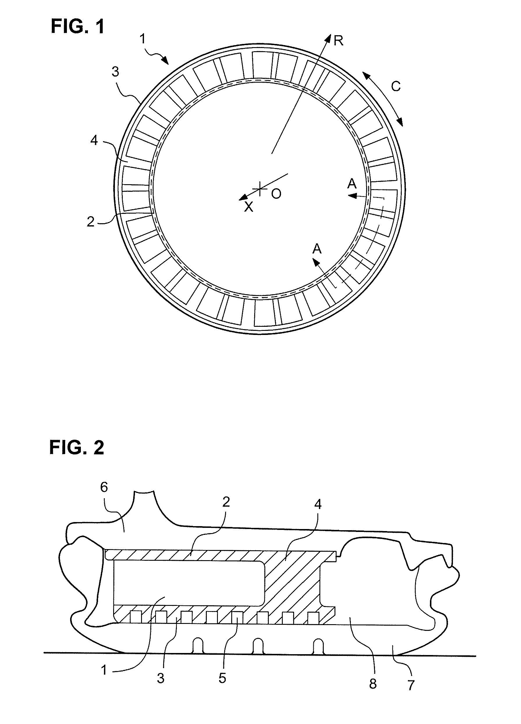
[0057]FIG. 1 shows, in a side view, a safety support 1 described in U.S. Pat. No. 6,564,842. This support essentially comprises three parts: a base 2, of generally annular shape; a substantially annular crown 3, intended to support the tread of a tire in the event of loss of pressure therefrom, with longitudinal grooves 5 (optionally) on its radially outer wall; and an annular body 4 for connecting the base and the crown.

[0058]FIG. 1 also specifies the geometric conventions used in the present application. The axis X passing through O is the axis of rotation of the support (axis X is perpendicular to the plane of FIG. 1). After the support has been mounted in the cavity of a tire and around a rim, the axis X is also the common axis of rotation of the support, the tire and the rim. The direction R is a radial direction, that is to say, one passing through the axis X and perpendicular thereto. The direction C is a circumferential direction. At any point of the support, the tire or th...


PUM


Abstract

A safety support adapted to be mounted on a rim within a tire fitted on a vehicle, to support the tread of the tire in the event of a loss of inflation pressure. The safety support includes a substantially cylindrical base adapted to be fitted around the rim; a substantially cylindrical crown adapted to come into contact with the tread in the event of a loss of pressure, and leaving a clearance relative to the tread at rated pressure; an annular body for connecting the base and the crown. The support is produced, at least in part, by axially assembling a number of annular sections, such that each of the annular sections includes, regularly distributed over the circumference, connecting walls of substantially axial orientation extending at least over part of the annular body and adapted to cooperate with the connecting walls of the adjacent annular section(s) in order to axially assemble the annular sections.

Description

CROSS-REFERENCE TO RELATED APPLICATIONS [0001] This application is a continuation of International Application PCT / EP2004 / 012680, filed Nov. 10, 2004, which claims priority to French Patent Application 03 / 13169, filed Nov. 10, 2003, both of which are incorporated herein by reference in their entirety. BACKGROUND OF THE INVENTION [0002] 1. Field of the Invention [0003] The present invention relates to safety supports for mounting on a rim within a tire fitted on a vehicle, to support the tread of the tire in the event of a loss of inflation pressure. [0004] 2. Description of Related Art [0005] Attempts have been made for several decades to produce supports designed so as to permit minimal driving of the vehicle, under certain conditions (in particular low-speed conditions), for a certain distance (generally a very short one), despite a loss of inflation pressure from a tire or “LOP” which may be as much as a total loss of the pressure or “run flat”. Without the presence of such suppo...

Claims


Application Information

Patent Timeline
Patent Type & Authority Applications(United States)
IPC IPC(8): B60C17/02B60C17/06
CPCB60C17/06B60C17/061B60C17/041
Inventor COGNE, MICHAELRABY, PASCALSILVAIN, LUCIEN
Owner MICHELIN RECH & TECH SA
Why Eureka
Eureka Blog
Learn More