
Programmable power controller

a power controller and programmable technology, applied in the field of power controllers, can solve the problems of significant normal activity, increased electrical energy costs, and based on energy usag

Inactive Publication Date: 2006-11-09
GARDNER GROFF GREENWALD & VILLANUEVA P C
View PDF22 Cites 118 Cited by
  • Summary
  • Abstract
  • Description
  • Claims
  • Application Information

AI Technical Summary

Benefits of technology

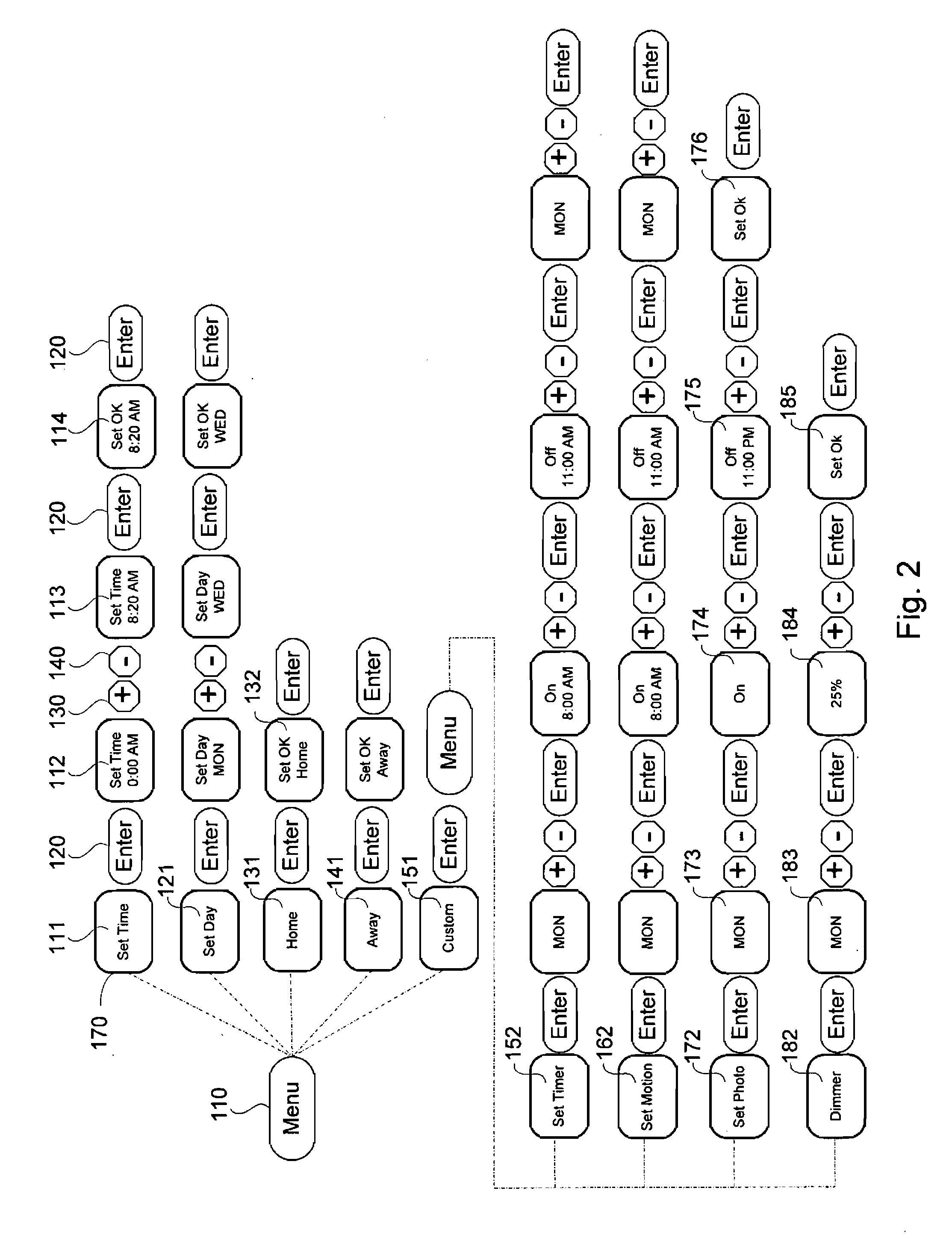
[0020] In yet another aspect, the present invention relates to a method for selectively providing power from a source of power to at least one load to operate in an area in response to plural environmental conditions and time periods. In one embodiment, the method includes the step of configuring a first detector for generating a detection signal responsive to an ambient light level being below the predetermined threshold value (e.g. a low light level), a second detector for generating a motion signal responsive to a movement in the area, and a microcontroller coupled to the first detector and the second detector for operatively controlling transmission of the source of power to the at least one load. The method further includes the step of programming a plurality of control parameters with a user interface communicating with a microcontroller. The plurality of control parameters comprises a predetermined threshold value of a light level, a first predetermined activation time, a second predetermined activation time, a first predetermined deactivation time, a second predetermined deactivation time, a first predetermined duration of time, a second predetermined duration of time, a third predetermined duration of time, and a predetermined power-on time. Moreover, the method includes the step of activating the first detector to monitor an ambient light level when the first predetermined activation time passes, and the second detector to monitor a movement in the area when the second predetermined activation time passes. Furthermore, the method includes the step of transmitting the power to the at least one load for a time period by a microcontroller when one of the detection signal and the motion signal is generated or the predetermined power-on time passes. The time period is defined by the first predetermined duration of time if the triggering signal is the detection signal, by the second predetermined duration of time if the triggering signal is the motion signal, or by the third predetermined duration of time if the predetermined power-on time passes. Additionally, the method includes the step of deactivating the first detector when the first predetermined deactivation time passes, and the second detector when the second predetermined deactivation time passes.
[0021] In one embodiment, the microcontroller is further configured such that when transmitting the power is triggered by the low light detection signal, any subsequent one a motion signal or expiration of the predetermined power-on time period generated during the first predetermined duration of time is ignored. Furthermore, when transmitting the power is triggered by the expiration of the predetermined power-on time period, any subsequent one of a low light detection signal or a motion signal generated during the third predetermined duration of time is ignored. Further still, when transmitting the power is triggered by the motion signal, any subsequent one of a low light detection signal or expiration of the predetermined power-on time period generated during the second predetermined duration of time is ignored, but a subsequent motion signal generated by the second detector during the time period renews the time period.

Problems solved by technology

As a result of dramatically increasing costs associated with electrical energy, devices have been developed that automatically activate and deactivate electrical appliances such as lights depending on when they are needed.
For the motion sensor based devices, however, there may be significant amounts of normal activity during the day time which would undesirably activate the lighting system which the motion detector is controlling.
Controlling a lighting system based on the amount of sunlight present has disadvantages based upon energy usage.
Another problem with controlled lighting systems is the effort required to override the timed, dusk to dawn, and motion detection controls.
On the other hand, few of these conventional power control devices are programmable.
Therefore, a heretofore unaddressed need exists in the art to address the aforementioned deficiencies and inadequacies.

Method used


Image

  • Programmable power controller
  • Programmable power controller
  • Programmable power controller

Examples


Embodiment Construction

[0042] The present invention is more particularly described in the following examples that are intended as illustrative only since numerous modifications and variations therein will be apparent to those skilled in the art. Various embodiments of the invention are now described in detail. Referring to the drawings, like numbers indicate like components throughout the views. As used in the description herein and throughout the claims that follow, the meaning of “a”, “an”, and “the” includes plural reference unless the context clearly dictates otherwise. Also, as used in the description herein and throughout the claims that follow, the meaning of “in” includes “in” and “on” unless the context clearly dictates otherwise.

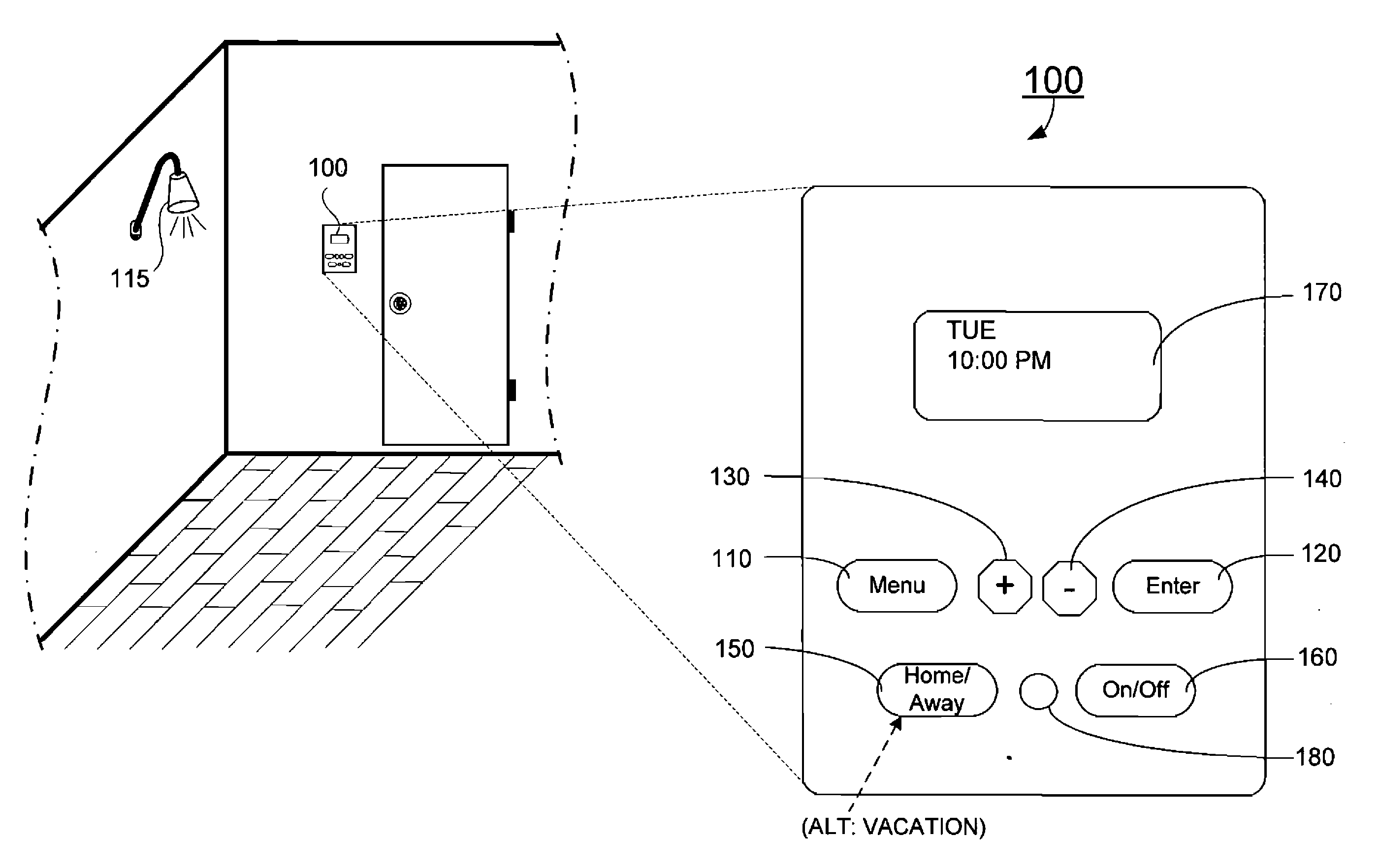
[0043] The description will be made as to the embodiments of the present invention in conjunction with the accompanying drawings of FIGS. 1-8. In accordance with the purposes of this invention, as embodied and broadly described herein, this invention, in one aspect, rel...


PUM


Abstract

A device connected between a source of power and at least one load for selectively providing power from the source of power to the at least one load to operate in an area responsive to an environmental condition in the area. In one embodiment, the device includes a home mode, an away mode, and a custom mode, and a user interface for selecting one of the home mode and the custom mode to be operated. The device further includes at least one timer for timing a plurality of predefined operations, a first detector for generating a low light detection signal responsive to an ambient light level being below a predetermined threshold value, a second detector for generating a motion signal responsive to detection of a movement in the area, a dimmer for adjusting power supplying to the at least one load at a predetermined level, and a microcontroller coupled to the first detector and the second detector and coupled with the user interface for operatively controlling transmission of the source of power to the at least one load.

Description

CROSS-REFERENCE TO RELATED PATENT APPLICATION [0001] This application claims the benefit, pursuant to 35 U.S.C. §119(e), of U.S. provisional patent application Ser. No. 60 / 678,109 filed May 5, 2005, entitled “PROGRAMMABLE POWER CONTROLLER” by Alan Butler and Jeffrey Smith, which is incorporated herein by reference in its entirety.FIELD OF THE INVENTION [0002] The present invention generally relates to a power controller, and more particularly, to a programmable power controller connected between a source of power and at least one load for selectively providing power from the source of power to the at least one load to operate in an area thereof responsive to an environmental condition in the area. BACKGROUND OF THE INVENTION [0003] As a result of dramatically increasing costs associated with electrical energy, devices have been developed that automatically activate and deactivate electrical appliances such as lights depending on when they are needed. The most rudimentary devices com...

Claims


Application Information

Patent Timeline
Patent Type & Authority Applications(United States)
IPC IPC(8): H01H47/00
CPCH01H9/181Y02B20/42H05B37/0281H01H2300/04H05B47/16Y02B20/40
Inventor BUTLER, ALANSMITH, JEFFREY
Owner GARDNER GROFF GREENWALD & VILLANUEVA P C
Learn More