
Navigation systems and methods for wheeled objects

a technology for navigation systems and objects, applied in the direction of navigation instruments, instruments, manufacturing tools, etc., can solve the problems of accumulated navigation errors, high cost of gps systems and rf tags and receiver systems, and inability to meet the needs of users, so as to reduce the accumulation of navigation errors

Active Publication Date: 2006-11-02
GATEKEEPER SYST
View PDF58 Cites 256 Cited by
  • Summary
  • Abstract
  • Description
  • Claims
  • Application Information

AI Technical Summary

Benefits of technology

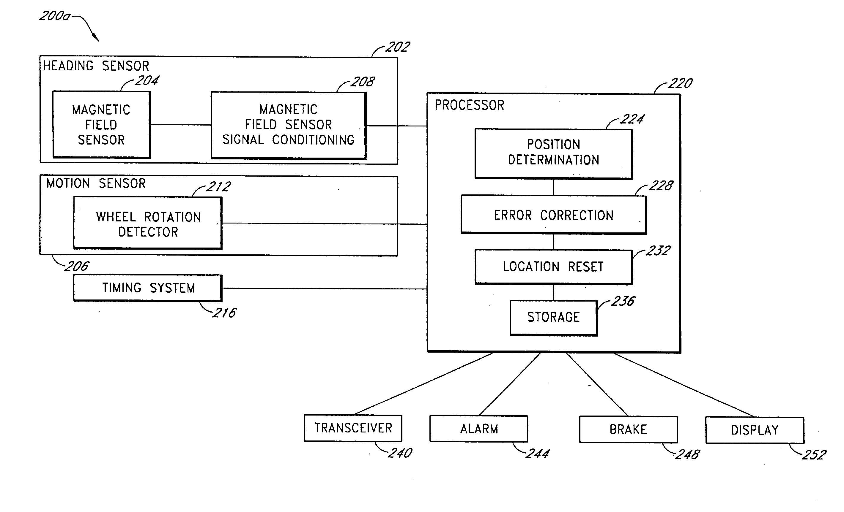
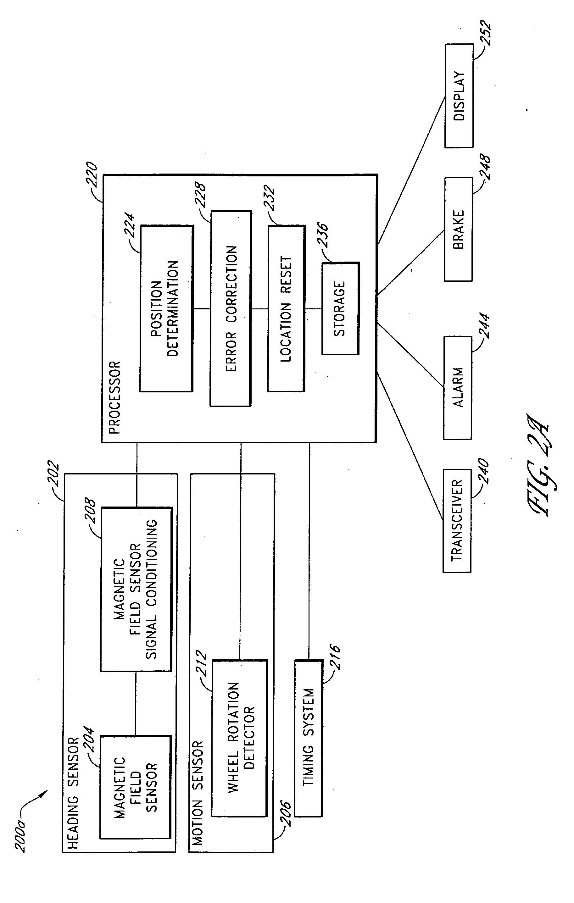
[0007] A navigation system uses a dead reckoning method to estimate an object's present position relative to one or more prior positions. In some embodiments, the dead reckoning method determines a change in position from the object's heading and speed during an elapsed time interval. In embodiments suitable for use with wheeled objects, the dead reckoning method determines the change in position by measuring the heading and the amount of wheel rotation. In a preferred embodiment, the heading is determined with reference to the Earth's magnetic field by disposing magnetic sensors in or on the object. Error correction and position reset procedures may be implemented to reduce accumulated navigational error. In preferred embodiments, some or all of the navigation system is disposed within a wheel of the object. In certain embodiments, the navigation system determines whether the object has exited a confinement area and activates an anti-theft system such as an alarm or a wheel locking mechanism. The navigation system can be configured to communicate with external markers and / or RF transmitters. In some embodiments, the markers comprise magnetic elements arranged to produce a magnetic signal indicating a direction or other suitable information.

Problems solved by technology

However, such methods are disadvantageous if the tracking area is large, which requires installation of many receivers, or if the tracking area contains structures that attenuate the tag transmissions.
However, GPS methods can fail if the GPS signal is blocked or if the visibility of satellites is interrupted.
Further, both GPS systems and RF tag and receiver systems can be expensive and difficult to implement.

Method used


Image

  • Navigation systems and methods for wheeled objects
  • Navigation systems and methods for wheeled objects
  • Navigation systems and methods for wheeled objects

Examples


example scenario

[0031] II. Example Scenario

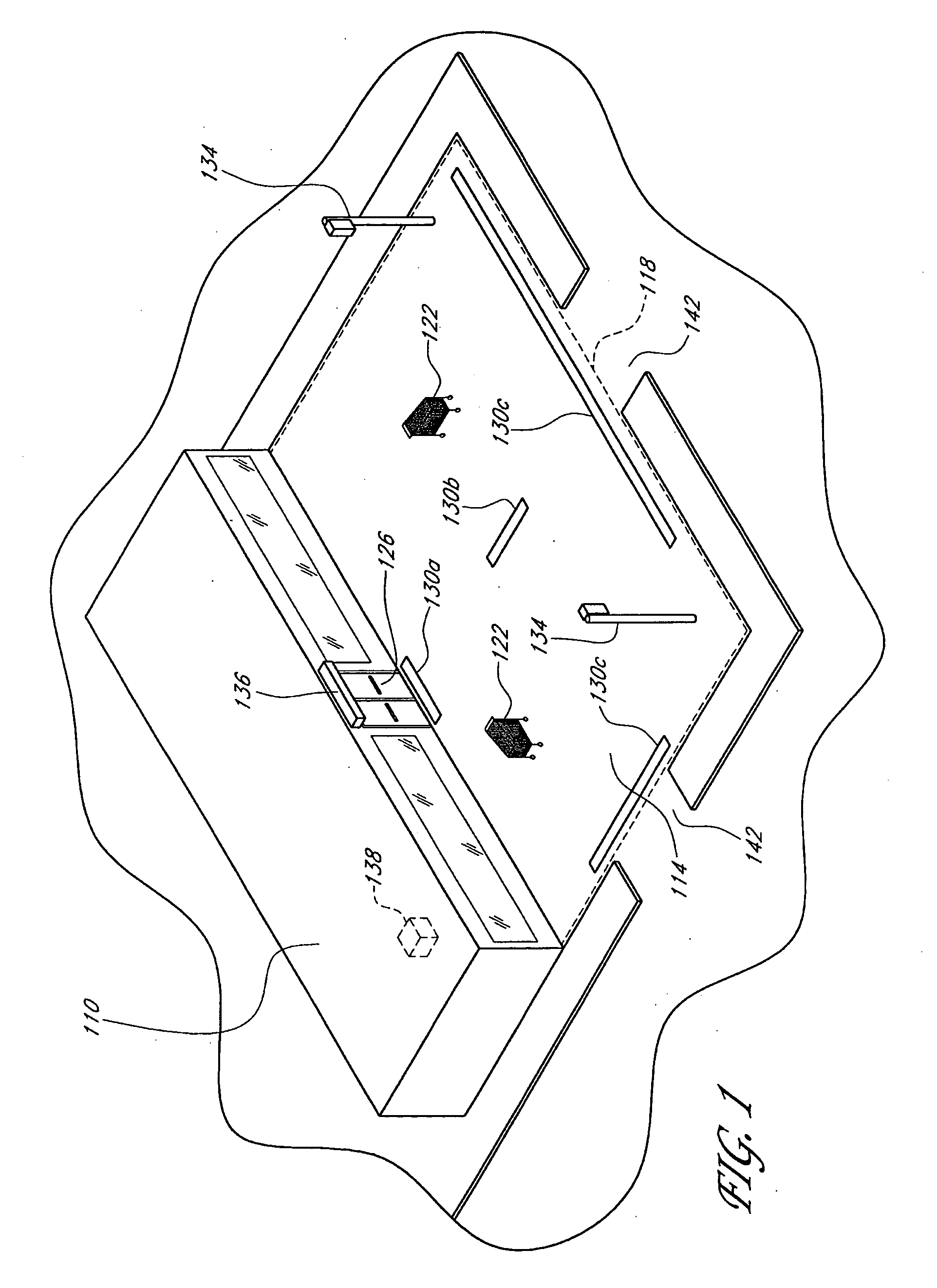
[0032] For purposes of illustration, a sample scenario in which an embodiment of the navigation systems and methods disclosed herein may be used will be presented with reference to FIG. 1. This sample scenario is intended to facilitate understanding of one embodiment and is not intended to limit the scope of the inventions disclosed and claimed.

[0033] In the sample scenario shown in FIG. 1, the navigation system is used as part of a loss prevention system by a retail store 110 to reduce the theft of shopping carts 122 from a tracking area 114. The tracking area 114 may comprise, for example, a portion of a parking lot adjacent to the store 110. An objective of the loss prevention system is to prevent, or at least reduce, the unauthorized transport of carts 122 across a boundary (or perimeter) 118 of the lot 114. In one embodiment of the loss prevention system, each cart 122 may include an anti-theft system comprising, for example, an alarm or a mechanism ...


PUM

PropertyMeasurementUnit
Diameteraaaaaaaaaa
Forceaaaaaaaaaa
Magnetic fieldaaaaaaaaaa

Abstract

A navigation system uses a dead reckoning method to estimate an object's present position relative to one or more prior positions. In some embodiments, the dead reckoning method determines a change in position from the object's heading and speed during an elapsed time interval. In embodiments suitable for use with wheeled objects, the dead reckoning method determines the change in position by measuring the heading and the amount of wheel rotation. Some or all of the components of the navigation system may be disposed within a wheel, such as a wheel of a shopping cart.

Description

CROSS-REFERENCE TO RELATED APPLICATIONS [0001] This application claims the benefit under 35 U.S.C. § 119(e) of U.S. Provisional Patent Application Nos. 60 / 663,147, 60 / 663,327, and 60 / 663,195, all filed on Mar. 18, 2005, the disclosures of which are hereby incorporated by reference. This application is being filed concurrently with the following non-provisional applications, the disclosures of which are additionally hereby incorporated by reference: U.S. patent application Ser. No. ______, filed Mar. 20, 2006, titled POWER GENERATION SYSTEMS AND METHODS FOR WHEELED OBJECTS (hereinafter “the Power Generation Patent Application”), and U.S. patent application Ser. No. 11 / 277,016, filed Mar. 20, 2006, titled TWO-WAY COMMUNICATION SYSTEM FOR TRACKING LOCATIONS AND STATUSES OF WHEELED VEHICLES (hereinafter “the Two-Way Communication Patent Application”).BACKGROUND [0002] 1. Field [0003] The present disclosure relates to determining the location of an object from its speed and direction of ...

Claims


Application Information

Patent Timeline
IPC IPC(8): G01C21/00H04W4/02H04W4/024H04W4/029
CPCA47F10/04Y10T29/49826B60T7/18B62B3/14B62B3/1404B62B5/0423B62B5/048G01C21/00G01C21/12G06Q10/08G08B13/2434G08B13/2448G08B13/2482G08G1/20H02K7/1846B60T7/16H04W4/028G01C21/206Y10T16/195B60K25/08G08B13/2474G08B13/246G08B13/2462G08B13/2477H04W4/029H04W4/02B62B3/1424H04W4/024B62B3/1492B62B5/0003B62B5/0438B62B3/1412G06K7/10366
Inventor CARTER, SCOTT J.HANNAH, STEPHEN E.JAMES, JESSE M.
Owner GATEKEEPER SYST
Learn More