
Spinal stabilization using bone anchor and anchor seat with tangential locking feature

a technology of bone anchor and tangential locking feature, which is applied in the field of vertebral stabilization of the spine, can solve the problems of compromising the quality of life of a person, the most common and often debilitating conditions affecting millions of people, and back pain

Active Publication Date: 2006-10-19
ALTUS PARTNERS
View PDF28 Cites 264 Cited by
  • Summary
  • Abstract
  • Description
  • Claims
  • Application Information

AI Technical Summary

Benefits of technology

[0015] In accordance with one or more embodiments of the present invention, a stabilization system for implantation in a patient includes: a bone anchor including a head having a contour; and a tulip including: (i) a base having an outer surface and an inner surface defining a volume for receiving the head, the contour of the head being of substantially complementary shape such that the tulip may articulate about the head, (ii) a first opening operable to permit a neck extending from the head to articulate there-within and exit the base through the first opening, and (iii) a second opening extending through the base transversely with respect to the first opening, and defining a profile that permits insertion of the head into the volume of the base at substantially one orientation of the head with respect to the profile, and does not permit insertion or removal of the head with respect to the volume of the base in substantially any other orientation of the head with respect to the profile.
[0016] In accordance with one or more embodiments of the present invention, a bone anchor includes: a head; a neck depending from the head; and a shaft extending away from the neck and being operable for connection to a bone of a patient, wherein the neck includes at least one bend such that the head is transversely oriented with respect to the shaft.
[0017] In accordance with one or more embodiments of the present invention, a tool includes: a first shaft having a proximal end and a distal end, the first shaft including a rod engagement element at the distal end that is operable to releasably and rotationally engage a stabilization rod used to interconnect a plurality of bone anchors coupled to one or more bones of a patient; a second shaft having a proximal end and a distal end, the proximal end of the second shaft being pivotally coupled to the first shaft at a position intermediate between the proximal and distal ends thereof, the distal end of the second shaft including a hitch element operable to permit connection of the tool a given one of the bone anchors, wherein: a force applied to the handle produces a torque at the proximal end of the second shaft, with the rod engagement element being at a fulcrum position, that transfers the torque into a translational force at the hitch ele

Problems solved by technology

Back pain is one of the most common and often debilitating conditions affecting millions of people in all walks of life.
Approximately half of those suffering from persistent back pain are afflicted with chronic disabling pain, which seriously compromises a person's quality of life and is the second most common cause of worker absenteeism.
Further, the cost of treating chronic back pain is very high, even though the majority of sufferers do not receive treatment due to health risks, limited treatment options and inadequate therapeutic results.
Thus, chronic back pain has a significantly adverse effect on a person's quality of life, on industrial productivity, and on heath care expenditures.
However, in many cases, and in particular, in cases involving fusion across the lumbosacral articulation and when there are many levels involved, pseudoarthrosis is a problem.
However, following the surgical procedure, fusion takes additional time to achieve maximum stability and a spinal fixation device is typically used to support the spinal column until a desired level of fusion is achieved.
A common problem with spinal fixation is the question of how to secure the fixation device to the spine without damaging the spinal cord.
This complicates the surgical procedure and increases the likelihood that a misalignment results during the tightening process.
Among the problems with the apparatus of U.S. Pat. No. 6,755,830 is that the head of the bone screw may become easily disengaged from the first component through the side opening thereof.
Therefore, conventional spinal fixation devices have not provided a satisfactory solution to the problems associated with curing spinal diseases.
Additionally, existing fixation devices utilize components that are not proven to provide long-term stability and durability, and are cumbersome and overly complex in terms of how they are adjusted and / or attach to the vertebral bones.

Method used


Image

  • Spinal stabilization using bone anchor and anchor seat with tangential locking feature
  • Spinal stabilization using bone anchor and anchor seat with tangential locking feature
  • Spinal stabilization using bone anchor and anchor seat with tangential locking feature

Examples


Embodiment Construction

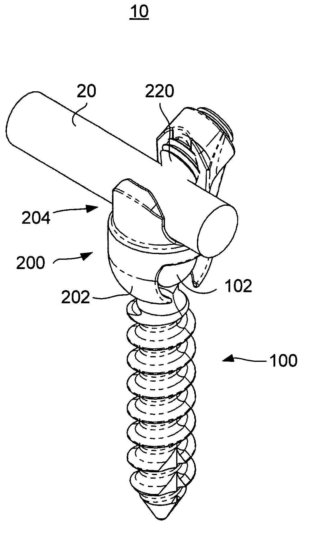
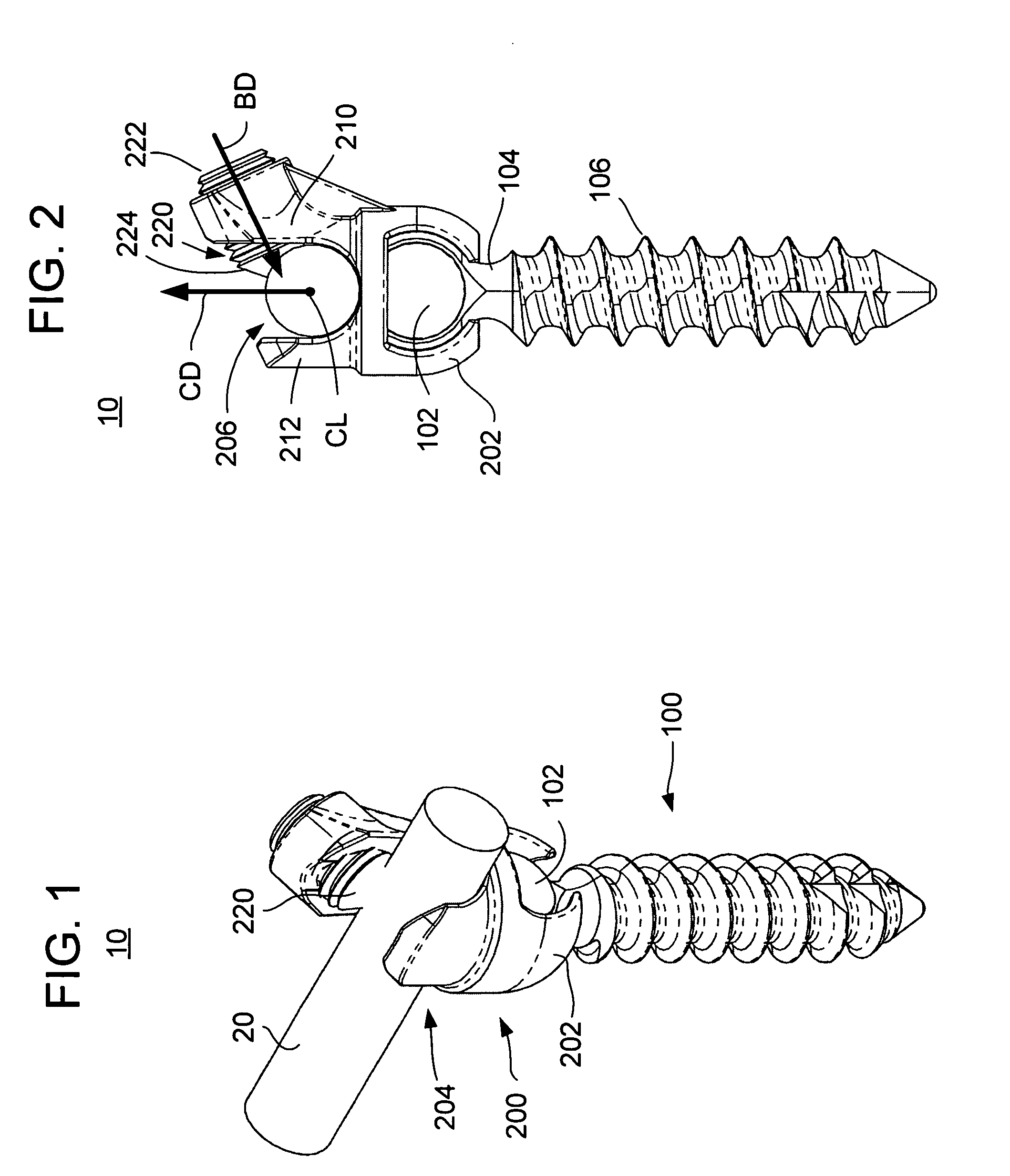
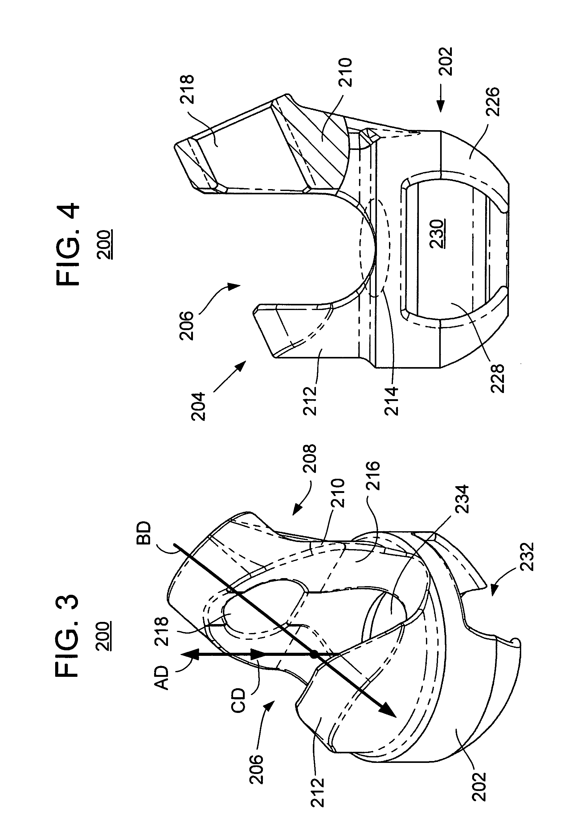
[0044]FIGS. 1-4 illustrate an embodiment of a spinal stabilizer system 10 in accordance with one or more aspects of the present invention. In use, it is understood that respective pairs of the stabilizing systems 10 may secure an elongate element, such as a stabilization rod, for internal fixation of respective bones of a patient, such as vertebrae of the spine.

[0045] The system 10 includes an anchor 100 and an anchor seat (or tulip) 200 that cooperate to fix a portion of a rod 20 to a bone. The bone anchor 100 includes a head 102, a neck 104, and a shaft 106, where the neck 104 interconnects the head 102 and the shaft 106. The shaft 106 extends away from the head 102 and is operable for connection to the bone of the patient. For example, the shaft 106 may include threads that may engage a bore made in the bone such that the anchor 100 is secured to the bone of the patient. In this embodiment, the bone anchor 100 and the tulip 200 are two separate pieces that are coupled together. ...


PUM


Abstract

A stabilization system for implantation in a patient includes: a bone anchor including a head and a shaft, the shaft extending away from the head in a bone insertion direction and being operable for connection to a bone of the patient; and a tulip including: at least one channel having an opening for receiving an elongate member, the opening being oriented in a receiving direction having at least a component thereof substantially opposite to the bone insertion direction of the anchor, and (ii) a fastening mechanism operable to apply a tangential load on the elongate member to maintain the elongate member within the channel, wherein the tangential load is transverse to at least the receiving direction.

Description

CROSS REFERENCE TO RELATED APPLICATIONS [0001] This application claims the benefit of U.S. Provisional Patent Application No. 60 / 658,227, filed Mar. 3, 2005, the entire disclosure of which is hereby incorporated by reference.BACKGROUND OF THE INVENTION [0002] The present invention is directed to vertebral stabilization of a spine using one or more rods anchored onto the vertebrae. [0003] Back pain is one of the most common and often debilitating conditions affecting millions of people in all walks of life. Today, it is estimated that over ten million people in the United States alone suffer from persistent back pain. Approximately half of those suffering from persistent back pain are afflicted with chronic disabling pain, which seriously compromises a person's quality of life and is the second most common cause of worker absenteeism. Further, the cost of treating chronic back pain is very high, even though the majority of sufferers do not receive treatment due to health risks, limit...

Claims


Application Information

Patent Timeline
IPC IPC(8): A61F2/30
CPCA61B17/7032A61B17/7034A61B17/7037A61B17/7038A61B17/8875A61B17/8685A61B17/7079A61B17/7086A61B17/7041
Inventor ALBERT, TODD JAMESZUBOK, RAFAILKVITNITSKY, MIKHAIL
Owner ALTUS PARTNERS
Learn More