
Transceiver with closed loop control of antenna tuning and power level

a technology of closed loop control and power level, applied in the direction of transmission monitoring, electric programme control, instruments, etc., can solve the problems of significant power reduction, and achieve the effect of efficient transmission and receiving rf signals and maximum efficiency

Inactive Publication Date: 2006-10-19
GENTEX CORP
View PDF12 Cites 23 Cited by
  • Summary
  • Abstract
  • Description
  • Claims
  • Application Information

AI Technical Summary

Benefits of technology

[0006] According to one aspect of the present invention, a trainable transceiver is provided that efficiently transmits and receives RF signals at various frequencies. Another aspect of the present invention is to provide a trainable transceiver capable of dynamically tuning an antenna for maximum efficiency at all frequencies of use. A further aspect of the present invention is to detect the RF voltage or power level of the transmission on the antenna and adjust it with reference to on-time characteristics or other variables. To achieve these and other advantages, and in accordance with the purpose of the invention as embodied and described herein, the trainable transceiver of the present invention includes a dynamically tunable antenna, a controller, a power level sense or detector circuit, and a signal generator.
[0008] Another aspect of the present invention is the ability to vary the transit power of the transceiver by varying its RF voltage or output power with reference to the duty cycle of the transmission. The present invention maximizes the transmission range for the transceiver which is dependent on the accuracy of tune on an integral tunable antenna and the control of the transmit power level. U.S. Pat. No. 5,699,054 discloses such an antenna and is incorporated by reference herein.

Problems solved by technology

However, due to the narrow bandwidth limitations of the present invention, slight mistuning of a loop antenna can result in significant power reduction.

Method used


Image

  • Transceiver with closed loop control of antenna tuning and power level
  • Transceiver with closed loop control of antenna tuning and power level
  • Transceiver with closed loop control of antenna tuning and power level

Examples


Embodiment Construction

[0020] The following description of the present invention is merely exemplary in nature and is in no way intended to limit the invention or its uses. Moreover, the following description, while depicting a tunable transceiver designed to operate with a garage door mechanism, is, intended to adequately teach one skilled in the art to make and use the tunable transceiver with any similar type RF transmission and receiving applications.

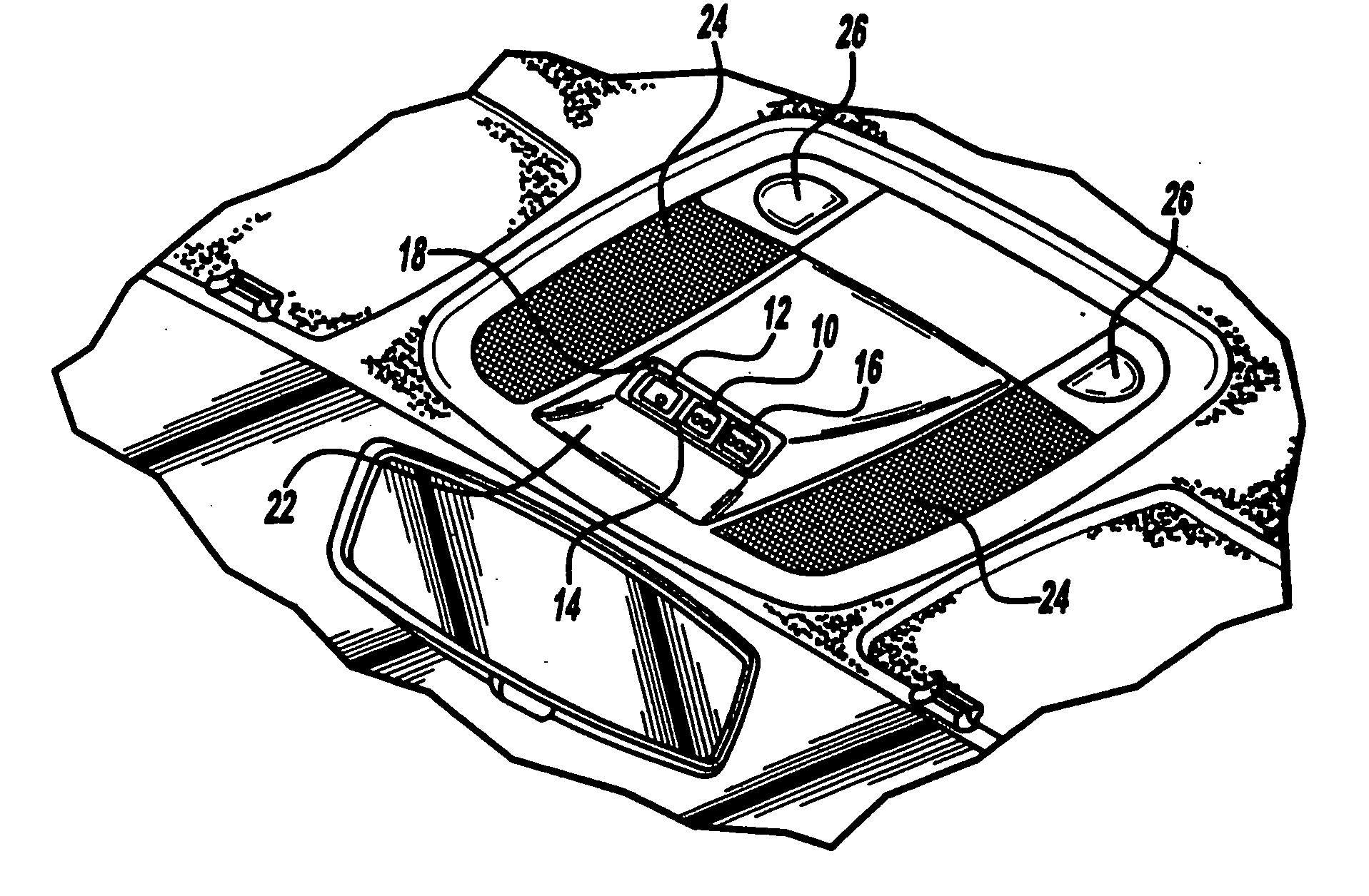
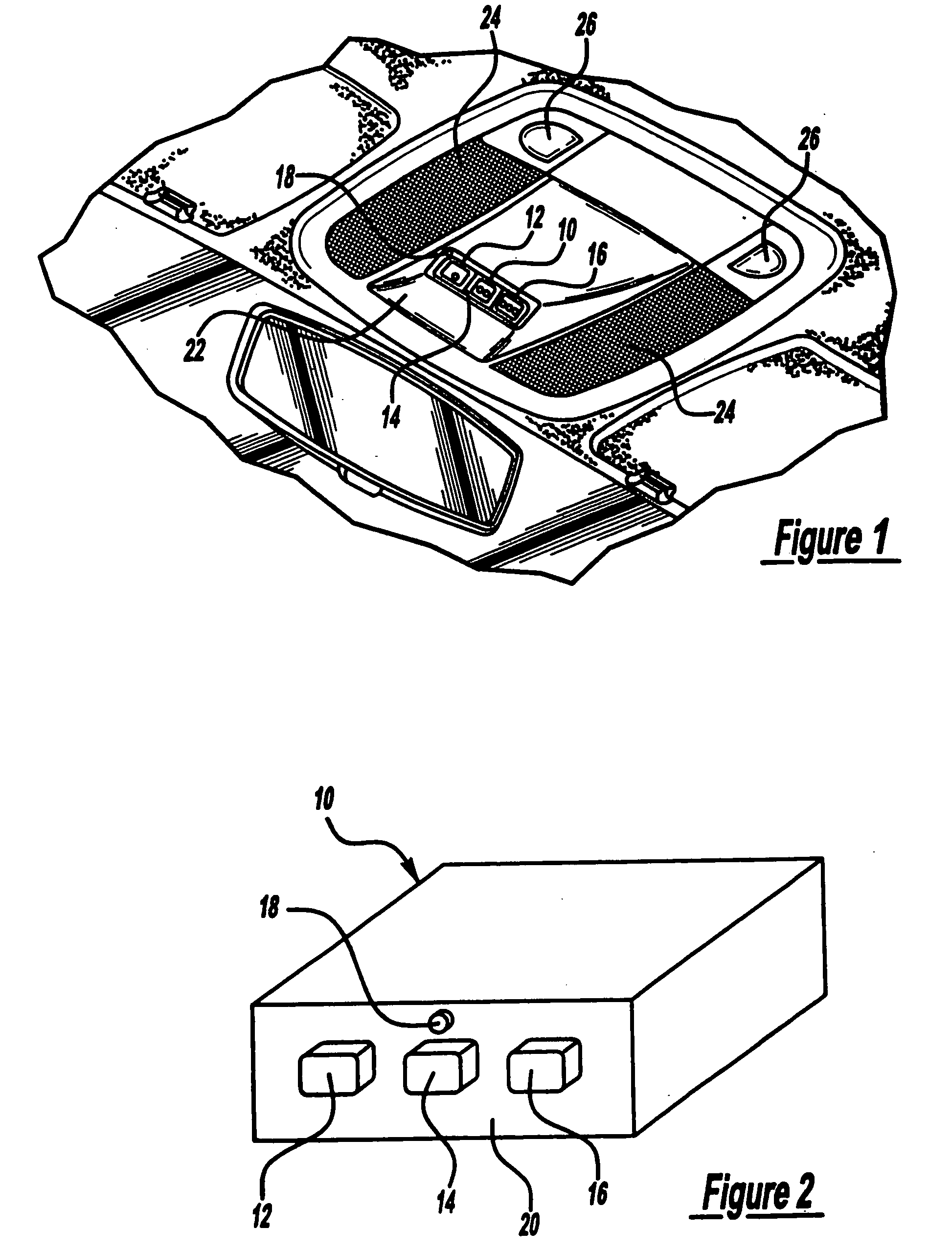
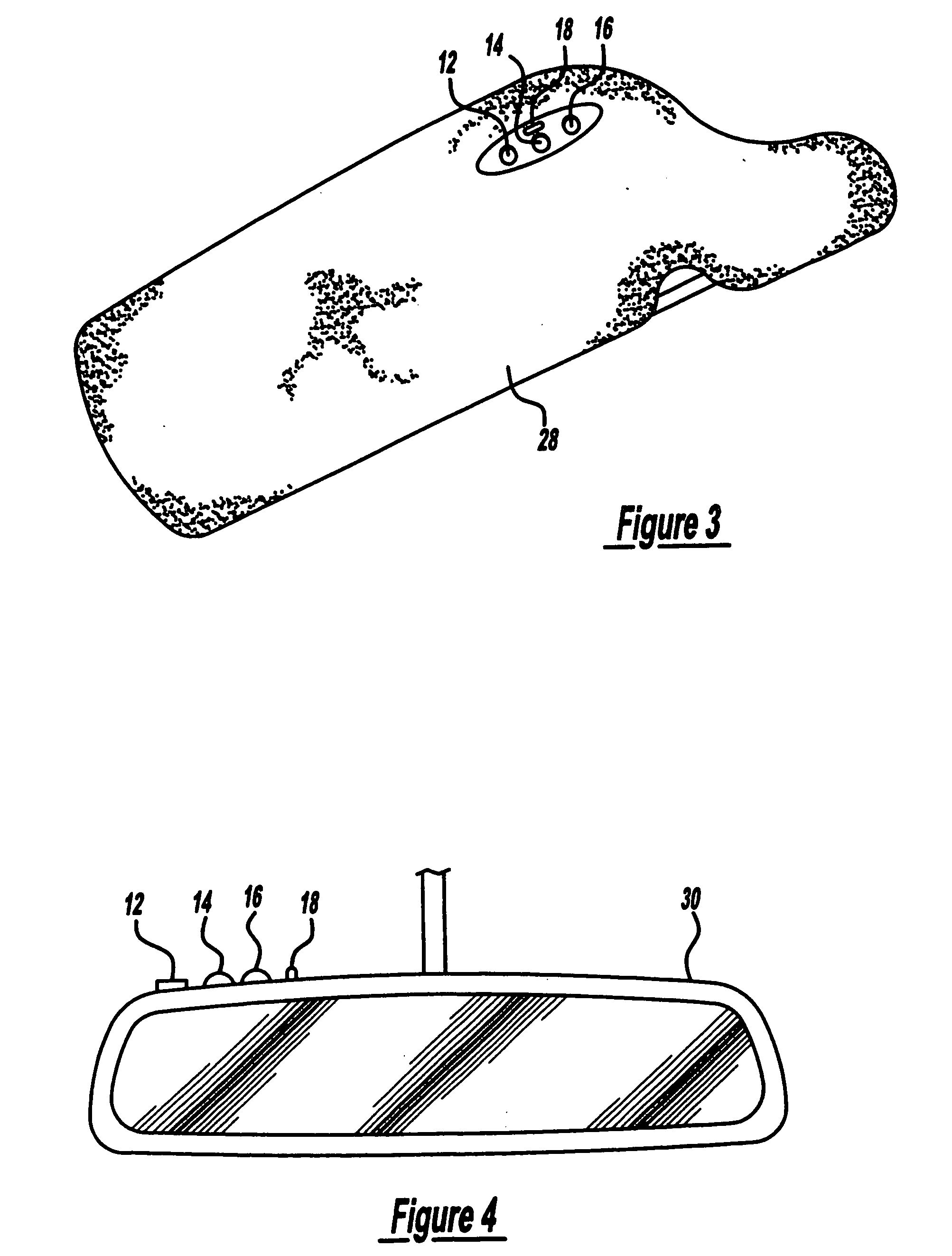
[0021]FIGS. 1 and 2 show a trainable transceiver 10 of the present invention. Trainable transceiver 10 includes three pushbutton switches 12, 14, and 16, a light emitting diode (LED) 18, and an electrical circuit board and associated circuits that may be mounted in a housing 20. As explained in greater detail below, the switches 12, 14, and 16 may each be associated with a separate garage door or other device to be controlled. The trainable transceiver housing 20 is preferably of appropriate dimensions for mounting within a vehicle accessory such as an o...


PUM


Abstract

A trainable transceiver for learning and transmitting an activation signal that includes an RF carrier frequency modulated with a code for remotely actuating a device, such as a garage door opener. The trainable transceiver preferably includes a controller, a signal generator, and a dynamically tunable antenna having a variable impedance that may be selectively controlled in accordance with a detector circuit signal. The detector circuit provides a measurement of the transmission power and is also used to vary the applied transmission power of the transceiver in response to operating and environmental parameters.

Description

BACKGROUND OF THE INVENTION [0001] Trainable transceivers for use with electrically operated garage door mechanisms are an increasingly popular home convenience. Such transceivers are typically permanently located in a vehicle and are powered by a vehicle's battery. These trainable transceivers are capable of learning the radio frequency, modulation scheme, and data code of an existing portable remote RF transmitter associated with an existing receiving unit located in the vehicle owner's garage. Thus, when a vehicle owner purchases a new car having such a trainable transceiver, the vehicle owner may train the transceiver to the vehicle owner's existing clip-on remote RF transmitter without requiring any new installation in the vehicle or home. Subsequently, the old clip-on transmitter can be discarded or stored. [0002] If a different home is purchased or an existing garage door opener is replaced, the trainable transceiver may be retrained to match the frequency and code of any new...

Claims


Application Information

Patent Timeline
Patent Type & Authority Applications(United States)
IPC IPC(8): H04B1/16G05B19/02G08C17/02H04B1/04
CPCE05Y2400/664E05Y2900/106G07C9/00309G07C9/00857E05F15/77G07C2009/00928G08C17/02G08C19/28G08C2201/20G07C2009/00349
Inventor BLAKER, DAVIDCARDWELL, MATTHEWDUCKWORTH, PAULHONECK, BRIAN
Owner GENTEX CORP
Learn More